404 Rockwell Automation Publication 2198-UM004D-EN-P - December 2022
Chapter 12 Motion Control Applications
Speed Fitting
This method creates a custom index profile on the slave that is based on the
motion of the master. This method works best when the master is moving at a
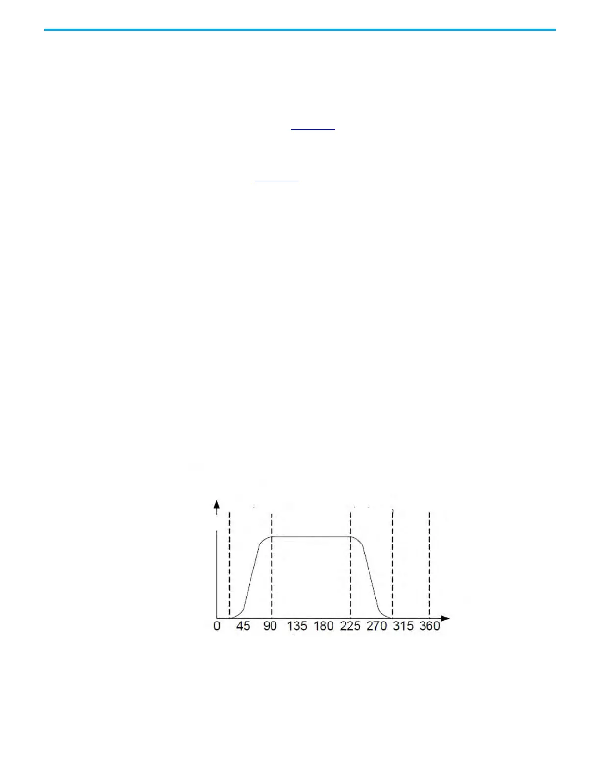
constant velocity. This method divides an E-CAM cycle into five zones: waiting
zone, acceleration zone, constant speed zone, deceleration zone, and stop
zone, as shown in Figure 213
. The proportion of each zone can be adjusted. The
E-CAM curve is designed from the position point of view. The corresponding
speed to the master-slave axis is determined by the position change per time
unit. The KNX5100C E-CAM table creation by using the speed fitting method is
shown in Figure 214
.
1. To plan the E-CAM curve, determine the proportion of waiting zone,
acceleration zone, constant speed zone, deceleration zone, and stop zone
in one cycle according to the required distribution.
2. Set the motion distance.
The total travel distance of the slave axis in one cycle, the unit is PUU.
3. Set the smoothness of the position curve at the turning point.
The larger the set value, the smoother the motor change during
acceleration and deceleration. A smoother curve extends the running
time in one cycle. The value of the S curve is usually the same as the
number of data points in the stop zone or less than the number of data
points in the stop zone.
4. After confirming that the curve is correct, click Download Table, then the
E-CAM curve is written to the data array.
Because the E-CAM data is stored in the Data Array, it is volatile, which
means that it does not persist through a power cycle. Once your E-CAM
table is finalized, check 'Burn to EEPROM when download' and click
Download. The data is saved and persists through a power cycle.
Figure 213 - Speed Zone Definition
Slave Axis Position
(PUU)
E-CAM angle °
Waiting Zone
Acceleration
Zone
Constant
Speed
Zone
Deceleration
Zone
Stop
Zone

 Loading...


