Nested vectored interrupt controller (NVIC) RM0453
500/1461 RM0453 Rev 1
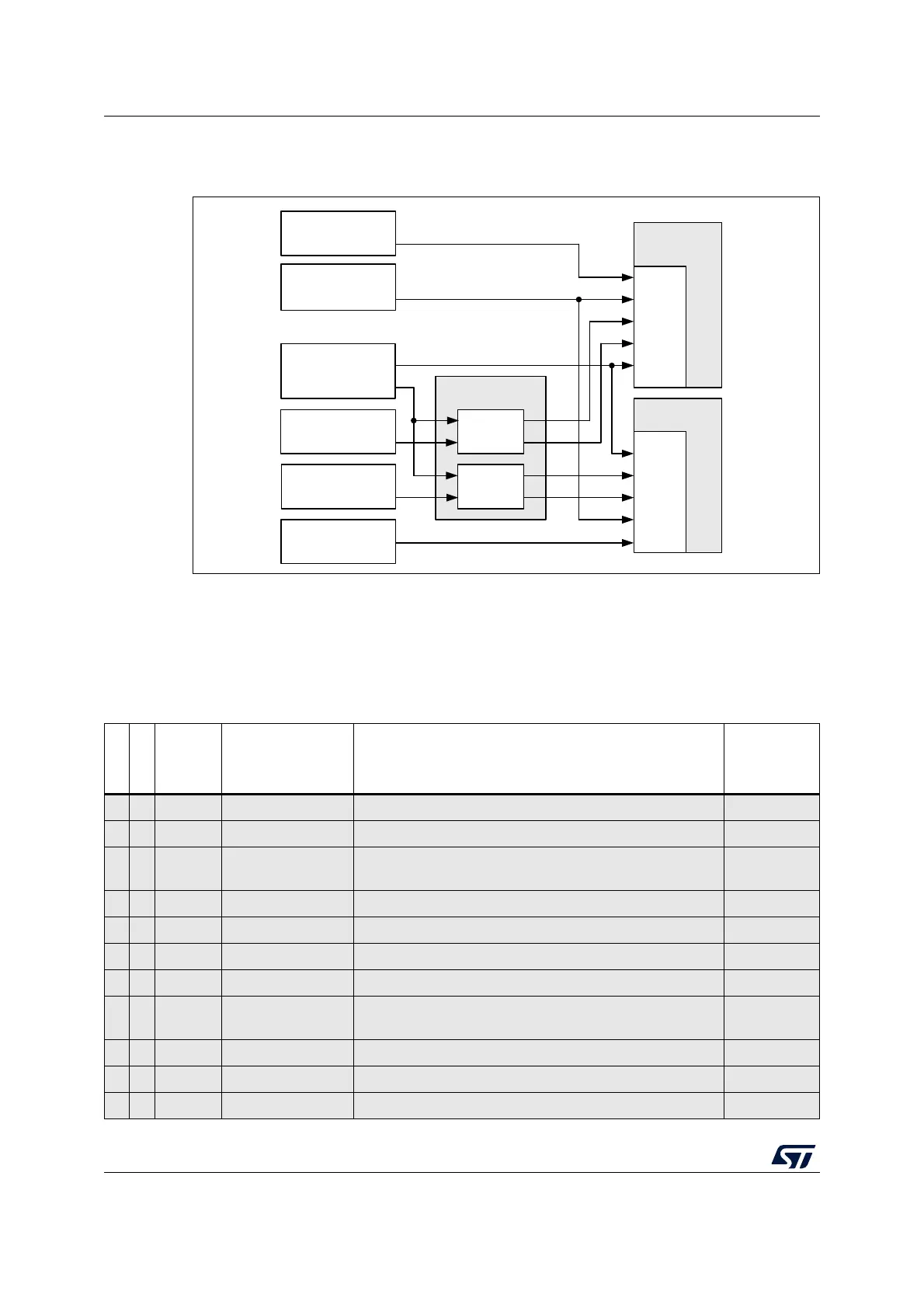
The interrupt block diagram is shown in the figure below.
Figure 53. Interrupt block diagram
15.3 Interrupt and exception vectors
The CPU1 and CPU2 vector tables are given respectively in Table 89 and Table 90 (shaded
cells indicate the processor exceptions).
MSv60391V1
CPU1
CPU2
NVIC
NVIC
SYSCFG
C2IMRn
C1IMRn
Peripheral
interrupt
Peripheral
interrupt
Peripheral
interrupt
Peripheral
interrupt
Peripheral
interrupt
AIEC
interrupt
interrupt
Table 89. CPU1 vector table
Position
Priority
Type of
priority
Acronym Description
(1)(2)
Address
- - - - Reserved 0x0000 0000
- -3 Fixed Reset Reset 0x0000 0004
- -2 Fixed NMI
Non maskable interrupt HSE32 CSS, Flash ECC and
SRAM2 parity
0x0000 0008
- -1 Fixed HardFault All classes of fault 0x0000 000C
- 0 Settable MemManager Memory manager 0x0000 0010
- 1 Settable BusFault Prefetch fault, memory access fault 0x0000 0014
- 2 Settable UsageFault Undefined instruction or illegal state 0x0000 0018
- - - - Reserved
0x0000 001C
0x0000 0028
- 3 Settable SVCall System service can via SWI instruction 0x0000 002C
- 4 Settable Debug Debug monitor 0x0000 0030
- - - - Reserved 0x0000 0034

 Loading...


