RM0453 Rev 1 1367/1461
RM0453 Debug support (DBG)
1448
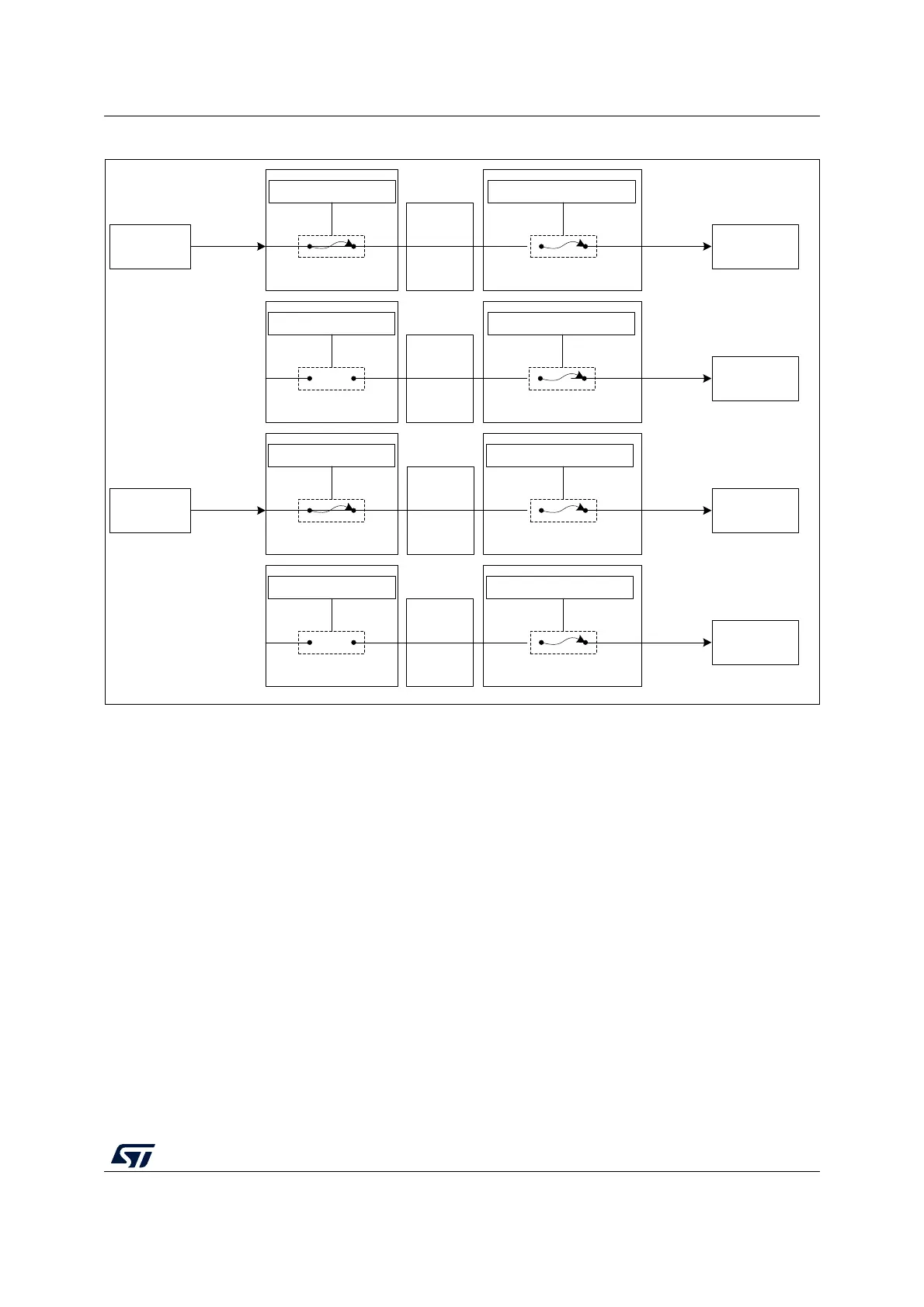
Figure 389. Cross trigger configuration example
The steps detailed below force the processors to restart simultaneously:
1. Clear the debug request by writing 0x01, then 0x00, to the CTI_INTACKR register in
each CTI.
2. Cause a pulse on channel 1 by writing 0x02 to the CTI_APPPULSER register in either
CTI. This generates a restart request to both processors.
Note: The debugger can also force both cores to stop simultaneously by writing 0x01 to the
CTI_APPPULSER register in either CTI, which generates a pulse on channel 0.
For more information on the CTI CoreSight component, refer to the Arm
®
CoreSight
SoC-400 Technical Reference Manual [2].
MSv60371V1
CTI_INENR0 = 0001 CTI_OUTENR0 = 0001
Channel 0
HALTED
EDBGRQ
CTI M4 CTI M0+CTM
Cortex-M4 Cortex-M0+
CTI_INENR1 = 0000 CTI_OUTENR1 = 0010
Channel 1
DBGRESTART
CTI M4 CTI M0+CTM
Cortex-M0+
CTI_INENR0 = 0001 CTI_OUTENR0 = 0001
HALTED
EDBGRQ
CTI M0+ CTI M4
Cortex-M0+ Cortex-M4
CTI_INENR1 = 0000 CTI_OUTENR1 = 0010
Channel 1
DBGRESTART
CTI M0+ CTI M4CTM
Cortex-M4
Channel 0
CTM

 Loading...


