RM0453 Rev 1 241/1461
RM0453 Power control (PWR)
276
Refer to the product datasheet for more details on voltage regulator and peripherals
operating conditions.
I/O states in LPRun mode
In LPRun mode, all I/O pins keep the same state as in Run mode.
Enter LPRun mode
To enter the LPRun mode, proceed as follows (refer to Table 47):
1. Jump into the SRAM and power down the Flash memory by setting the FPDR bit in the
Section 6.6.1: PWR control register 1 (PWR_CR1) (optional).
2. Disable HSE32 clock.
3. Decrease the HCLK clock frequencies below 2 MHz.
4. Force the regulator in low-power mode by setting the LPR bit in the PWR control
register 1 (PWR_CR1).
Exit LPRun mode
To exit the LPRun mode, proceed as follows (refer to Table 47):
1. Force the regulator in main mode by clearing the LPR bit in the PWR control register 1
(PWR_CR1).
2. Wait until REGLPF bit is cleared in the Power status register 2 (PWR_SR2).
3. Increase the HCLK clock frequency (enable HSE32 clock when needed).
6.5.3 Enter low-power mode
The MCU enters low-power mode following one of these events:
• when MCU executes the WFI (wait for interrupt)
• when MCU executes WFE (wait for event) instructions
• on return from ISR when the SLEEPONEXIT bit in the CPU system control register is
set
Low-power mode is only be entered if no interrupt or event is pending.
6.5.4 Exit low-power mode
From Sleep and Stop modes, the CPU exits low-power mode depending on the way the
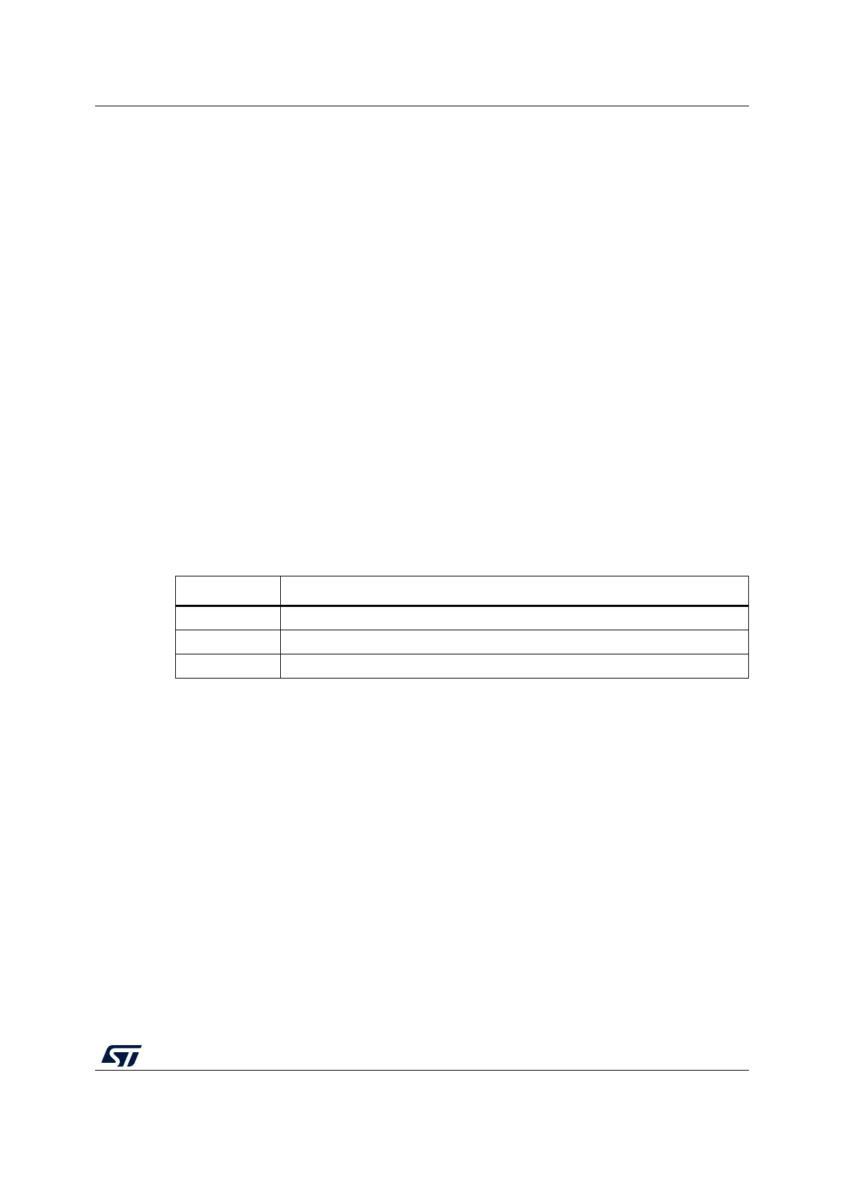
Table 47. LPRun
LPRun mode Description
Mode entry Decrease the system clock frequency below 2 MHz. LPR = 1.
Mode exit LPR = 0. Wait until REGLPF = 0. Increase the system clock frequency.
Wakeup latency Regulator wakeup time from low-power mode

 Loading...


