RM0453 Rev 1 871/1461
RM0453 General-purpose timer (TIM2)
901
Figure 234. Gating TIM2 with Enable of TIM1
Using one timer to start another timer
In this example, we set the enable of Timer 2 with the update event of Timer 1. Refer to
Figure 231 for connections. Timer 2 starts counting from its current value (which can be
non-zero) on the divided internal clock as soon as the update event is generated by Timer 1.
When Timer 2 receives the trigger signal its CEN bit is automatically set and the counter
counts until we write ‘0 to the CEN bit in the TIM2_CR1 register. Both counter clock
frequencies are divided by 3 by the prescaler compared to CK_INT (f
CK_CNT
= f
CK_INT
/3).
1. Configure TIM1 master mode to send its Update Event (UEV) as trigger output
(MMS=010 in the TIM1_CR2 register).
2. Configure the TIM1 period (TIM1_ARR registers).
3. Configure TIM2 to get the input trigger from TIM1 (TS=00000 in the TIM2_SMCR
register).
4. Configure TIM2 in trigger mode (SMS=110 in TIM2_SMCR register).
5. Start TIM1 by writing ‘1 in the CEN bit (TIM1_CR1 register).
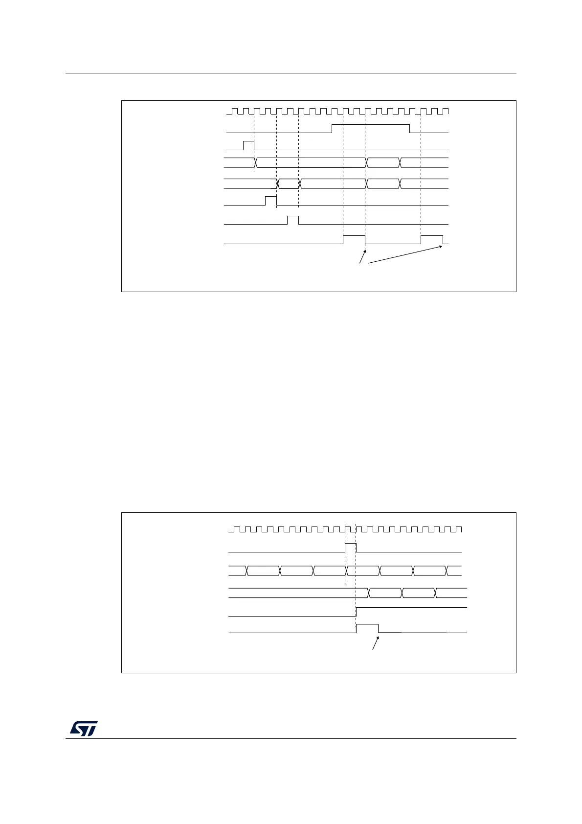
Figure 235. Triggering TIM2 with update of TIM1
MS32696V1
CK_INT
75 00
E7
TIM1-CNT_INIT
TIM1-CNT
AB
TIM2-CNT
TIM2-CNT_INIT
Write TIF = 0
01 02
E9E800
TIM1-CEN=CNT_EN
TIM2-write CNT
TIM2-TIF
MS32697V1
CK_INT
TIM2-CNT
FDTIM1-CNT
Write TIF = 0
TIM2-CEN=CNT_EN
TIM2-TIF
FE FF 00 01 02
46 47 4845
TIM1-UEV

 Loading...


