RM0453 Rev 1 801/1461
RM0453 Advanced-control timer (TIM1)
829
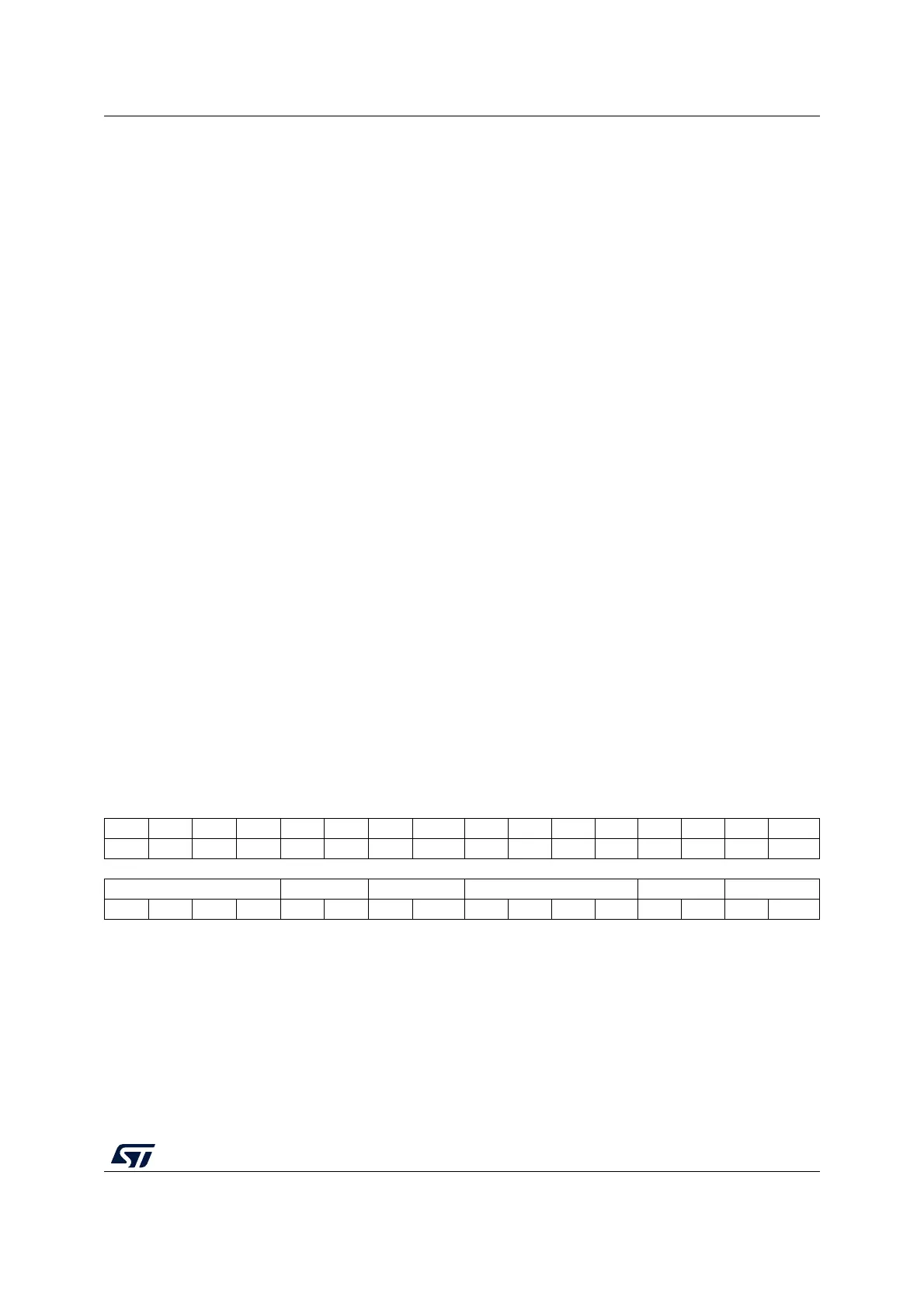
25.4.7 TIM1 capture/compare mode register 1 [alternate]
(TIM1_CCMR1)
Address offset: 0x18
Reset value: 0x0000 0000
The same register can be used for input capture mode (this section) or for output compare
mode (next section). The direction of a channel is defined by configuring the corresponding
CCxS bits. All the other bits of this register have a different function for input capture and for
output compare modes. It is possible to combine both modes independently (e.g. channel 1
in input capture mode and channel 2 in output compare mode).
Input capture mode:
Bit 2 CC2G: Capture/Compare 2 generation
Refer to CC1G description
Bit 1 CC1G: Capture/Compare 1 generation
This bit is set by software in order to generate an event, it is automatically cleared by
hardware.
0: No action
1: A capture/compare event is generated on channel 1:
If channel CC1 is configured as output:
CC1IF flag is set, Corresponding interrupt or DMA request is sent if enabled.
If channel CC1 is configured as input:
The current value of the counter is captured in TIMx_CCR1 register. The CC1IF flag is set,
the corresponding interrupt or DMA request is sent if enabled. The CC1OF flag is set if the
CC1IF flag was already high.
Bit 0 UG: Update generation
This bit can be set by software, it is automatically cleared by hardware.
0: No action
1: Reinitialize the counter and generates an update of the registers. The prescaler internal
counter is also cleared (the prescaler ratio is not affected). The counter is cleared if the
center-aligned mode is selected or if DIR=0 (upcounting), else it takes the auto-reload
value (TIMx_ARR) if DIR=1 (downcounting).
31 30 29 28 27 26 25 24 23 22 21 20 19 18 17 16
Res. Res. Res. Res. Res. Res. Res. Res. Res. Res. Res. Res. Res. Res. Res. Res.
1514131211109 8 7654321 0
IC2F[3:0] IC2PSC[1:0] CC2S[1:0] IC1F[3:0] IC1PSC[1:0] CC1S[1:0]
rw rw rw rw rw rw rw rw rw rw rw rw rw rw rw rw
Bits 31:16 Reserved, must be kept at reset value.
Bits 15:12 IC2F[3:0]: Input capture 2 filter
Refer to IC1F[3:0] description.
Bits 11:10 IC2PSC[1:0]: Input capture 2 prescaler
Refer to IC1PSC[1:0] description.

 Loading...


