RM0453 Rev 1 1411/1461
RM0453 Debug support (DBG)
1448
38.11.7 TPIU formatter synchronization counter register (TPIU_FSCR)
Address offset: 0x308
Reset value: 0x0000 0040
38.11.8 TPIU claim tag set register (TPIU_CLAIMSETR)
Address offset: 0xFA0
Reset value: 0x0000 000F
Bits 31:9 Reserved, must be kept at reset value.
Bit 8 TRIGIN: trigger on trigger in
1: Indicates a trigger in the trace stream when the TRIGIN input is asserted.
Bits 7:2 Reserved, must be kept at reset value.
Bit 1 ENFCONT: continuous formatting enable
Setting this bit to 0 in SWO mode bypasses the formatter and only ITM/DWT trace is output.
0: Continuous formatting disabled
1: Continuous formatting enabled
Bit 0 Reserved, must be kept at reset value.
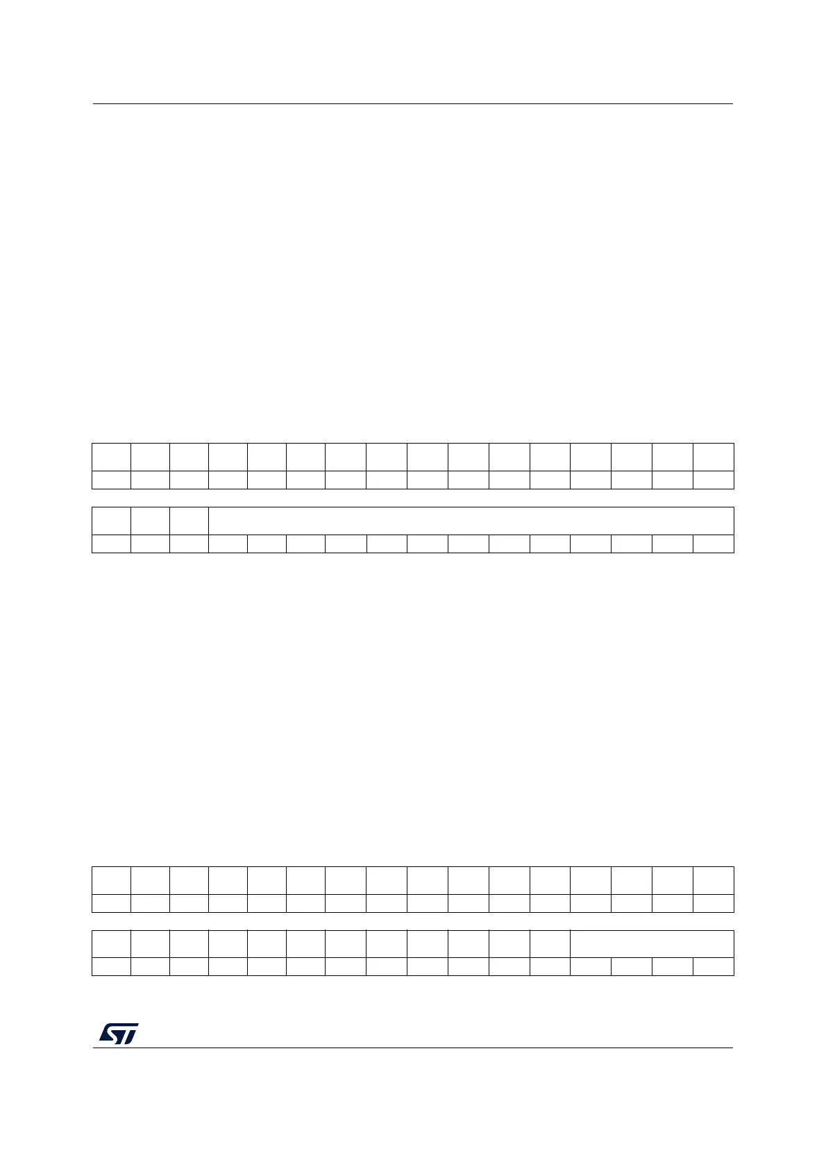
31 30 29 28 27 26 25 24 23 22 21 20 19 18 17 16
Res. Res. Res. Res. Res. Res. Res. Res. Res. Res. Res. Res. Res. Res. Res. Res.
1514131211109876543210
Res. Res. Res. CYCCOUNT[12:0]
rw rw rw rw rw rw rw rw rw rw rw rw rw
Bits 31:13 Reserved, must be kept at reset value.
Bits 12:0 CYCCOUNT[12:0]: enables effective use of different sized TPAs without wasting large
amounts of the storage capacity of the capture device
This counter contains the number of formatter frames since the last synchronization packet of
128 bits. It is a 12-bit counter with a maximum count value of 4096. This equates to
synchronization every 65536 bytes, that is, 4096 packets x 16 bytes per packet. The default
is set up for a synchronization packet every 1024 bytes, that is, every 64 formatter frames. If
the formatter is configured for continuous mode, full and half-word sync frames are inserted
during normal operation. Under these circumstances, the count value is the maximum
number of complete frames between full synchronization packets.
31 30 29 28 27 26 25 24 23 22 21 20 19 18 17 16
Res. Res. Res. Res. Res. Res. Res. Res. Res. Res. Res. Res. Res. Res. Res. Res.
1514131211109876543210
Res. Res. Res. Res. Res. Res. Res. Res. Res. Res. Res. Res. CLAIMSET[3:0]
rw rw rw rw

 Loading...


