Analog-to-digital converter (ADC) RM0453
538/1461 RM0453 Rev 1
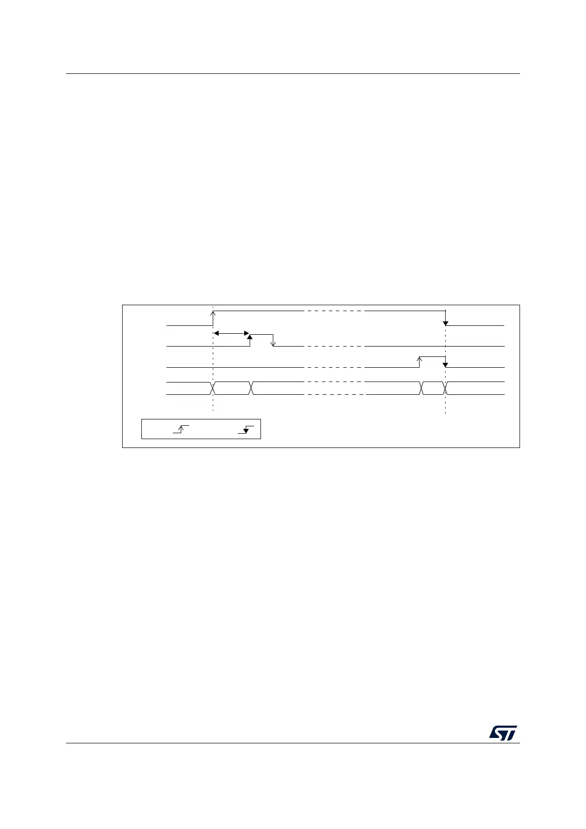
Follow this procedure to enable the ADC:
1. Clear the ADRDY bit in ADC_ISR register by programming this bit to 1.
2. Set ADEN = 1 in the ADC_CR register.
3. Wait until ADRDY = 1 in the ADC_ISR register (ADRDY is set after the ADC startup
time). This can be handled by interrupt if the interrupt is enabled by setting the
ADRDYIE bit in the ADC_IER register.
Follow this procedure to disable the ADC:
1. Check that ADSTART = 0 in the ADC_CR register to ensure that no conversion is
ongoing. If required, stop any ongoing conversion by writing 1 to the ADSTP bit in the
ADC_CR register and waiting until this bit is read at 0.
2. Set ADDIS = 1 in the ADC_CR register.
3. If required by the application, wait until ADEN = 0 in the ADC_CR register, indicating
that the ADC is fully disabled (ADDIS is automatically reset once ADEN
= 0).
4. Clear the ADRDY bit in ADC_ISR register by programming this bit to 1 (optional).
Figure 61. Enabling/disabling the ADC
Note: In Auto-off mode (AUTOFF = 1) the power-on/off phases are performed automatically, by
hardware and the ADRDY flag is not set.
MS30264V2
t
STAB
ADEN
DRDY
ADDIS
ADC
OFF Startup RDY CONVERTING CH RDY
OFF
by H/W
by S/W
REQ
-OF
stat

 Loading...


