RM0453 Rev 1 643/1461
RM0453 True random number generator (RNG)
649
The user can enable or disable the above interrupt sources individually by changing the
mask bits or the general interrupt control bit IE in the RNG_CR register. The status of the
individual interrupt sources can be read from the RNG_SR register.
Note: Interrupts are generated only when RNG is enabled.
22.5 RNG processing time
In NIST compliant configuration, the time between two sets of four 32-bit data is either:
• 412 AHB cycles if f
AHB
< f
threshold
(conditioning stage is limiting), or
• 256 RNG cycles f
AHB
≥ f
threshold
(noise source stage is limiting).
With f
threshold
= 1.6 x f
AHB
, e.g. 77 MHz if f
RNG
= 48 MHz.
Note: When CLKDIV is different from zero, f
RNG
must take into account the internal divider ratio.
22.6 RNG entropy source validation
22.6.1 Introduction
In order to assess the amount of entropy available from the RNG, STMicroelectronics has
tested the peripheral using German BSI AIS-31 statistical tests (T0 to T8), and NIST SP800-
90B test suite. The results can be provided on demand or the customer can reproduce the
tests.
22.6.2 Validation conditions
STMicroelectronics has tested the RNG true random number generator in the following
conditions:
• RNG clock rng_clk= 48 MHz
• RNG configurations described in Table 131. Note that only configuration A can be
certified NIST SP800-90B.
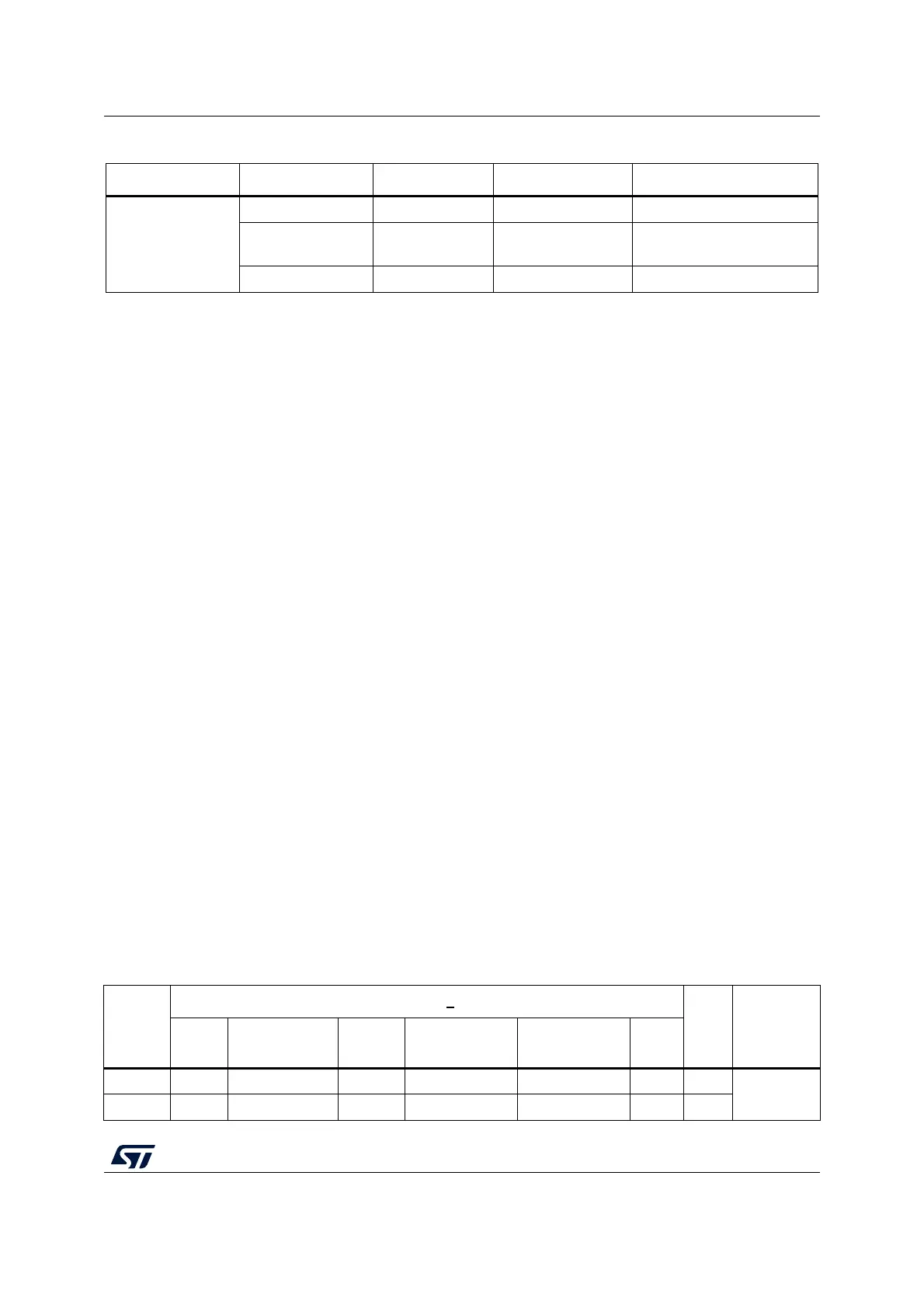
Table 130. RNG interrupt requests
Interrupt acronym Interrupt event Event flag Enable control bit Interrupt clear method
RNG
Data ready flag DRDY IE None (automatic)
Seed error flag SEIS IE
Write 0 to SEIS or write
CONDRST to 1 then to 0
Clock error flag CEIS IE Write 0 to CEIS
Table 131. RNG configurations
RNG
Config
RNG_CR b
its
Nb
loop
(N)
RNG_HTCR
register
(1)
NISTC
bit
RNG_CONFIG1
[5:0]
CLKDIV
[3:0]
RNG_CONFIG2
[2:0]
RNG_CONFIG3
[3:0]
CED
bit
A 0 0x0F 0x0 0x0 0xD 0 2
0x0000
AA74
B 1 0x18 0x0 0x0 0x0 0 2

 Loading...


