Analog-to-digital converter (ADC) RM0453
558/1461 RM0453 Rev 1
18.7 Analog window watchdog (AWD1EN, AWD1SGL, AWD1CH,
ADC_AWDxCR, ADC_AWDxTR)
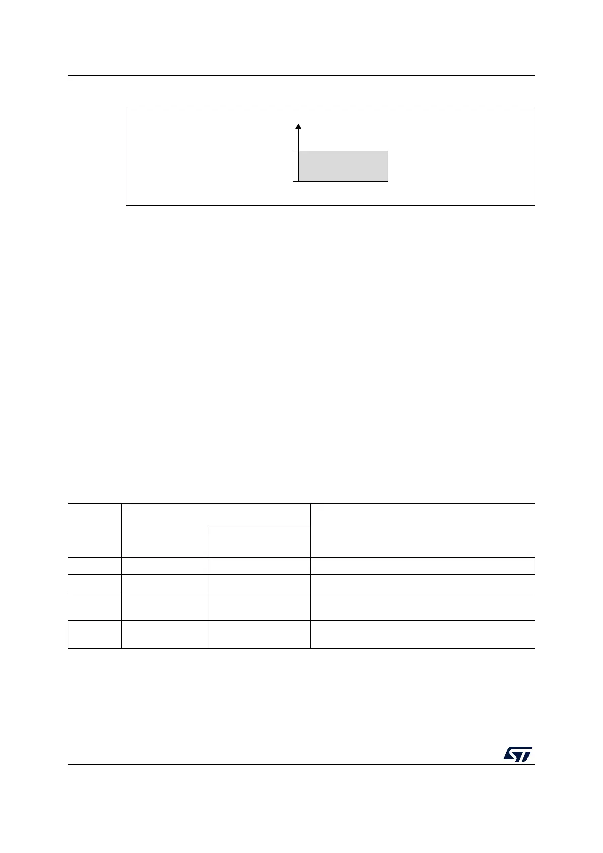
The three AWD analog watchdogs monitor whether some channels remain within a
configured voltage range (window).
18.7.1 Description of analog watchdog 1
AWD1 analog watchdog is enabled by setting the AWD1EN bit in the ADC_CFGR1 register.
It is used to monitor that either one selected channel or all enabled channels
(see Table 107:
Analog watchdog 1 channel selection)
remain within a configured voltage range (window) as
shown in Figure 76.
The AWD1 analog watchdog status bit is set if the analog voltage converted by the ADC is
below a lower threshold or above a higher threshold. These thresholds are programmed in
HT1[11:0] and LT1[11:0] bits of ADC_AWD1TR register. An interrupt can be enabled by
setting the AWD1IE bit in the ADC_IER register.
The AWD1 flag is cleared by software by programing it to 1.
When converting data with a resolution of less than 12-bit (according to bits DRES[1:0]), the
LSB of the programmed thresholds must be kept cleared because the internal comparison
is always performed on the full 12-bit raw converted data (left aligned).
Table 106 describes how the comparison is performed for all the possible resolutions.
Table 107 shows how to configure the AWD1SGL and AWD1EN bits in the ADC_CFGR1
register to enable the analog watchdog on one or more channels.
MS45396V1
Analog voltage
Higher threshold
Lower threshold
Guarded area
HTx
LTx
Table 106. Analog watchdog comparison
Resolution
bits
RES[1:0]
Analog Watchdog comparison between:
Comments
Raw converted
data, left aligned
(1)
Thresholds
00: 12-bit DATA[11:0] LTx[11:0] and HTx[11:0] -
01: 10-bit DATA[11:2],00 LTx[11:0] and HTx[11:0] The user must configure LTx[1:0] and HTx[1:0] to “00”
10: 8-bit DATA[11:4],0000 LTx[11:0] and HTx[11:0]
The user must configure LTx[3:0] and HTx[3:0] to
“0000”
11: 6-bit DATA[11:6],000000 LTx[11:0] and HTx[11:0]
The user must configure LTx[5:0] and HTx[5:0] to
“000000”
1. The watchdog comparison is performed on the raw converted data before any alignment calculation.

 Loading...


