Tamper and backup registers (TAMP) RM0453
1042/1461 RM0453 Rev 1
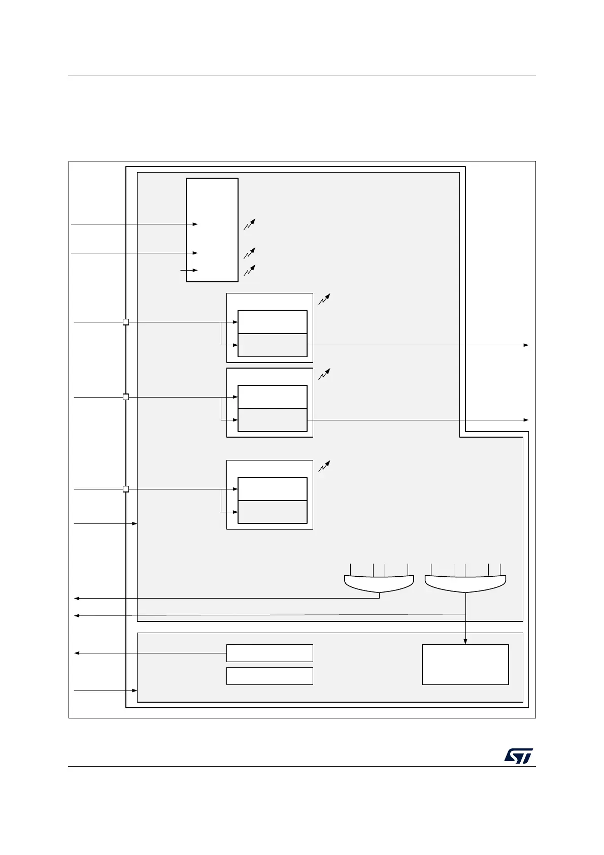
33.3 TAMP functional description
33.3.1 TAMP block diagram
Figure 274. TAMP block diagram
1. The number of external and internal tampers depends on products.
MSv50968V2
TAMP_IN1
tamp_pclk clock domain
Registers interface
tamp_pclk
IRQ interface
TAMP1F
Tamper detection
EDGE detection
LEVEL detection
TAMP2F
Tamper detection
EDGE detection
LEVEL detection
...
TAMPxF
(1)
Tamper detection
EDGE detection
LEVEL detection
...
Backup registers
tamp_it
tamp_erase
tamp_ker_ck
tamp_ker_ck clock domain
TAMP_IN2
TAMP_INx
tamp_trg1
tamp_trg2
Internal
tamper
detection
tamp_itamp1 ITAMP1F
...
tamp_itampy
Monotonic
counter
overflow
ITAMP1
...
ITAMPy
(1)
ITAMP8
ITAMPyF
ITAMP8F
...
TAMP1F when TAMP1NOER=0
TAMPxF when TAMPxNOER=0
...
ITAMP1F when ITAMP1NOER=0
ITAMPyF when ITAMPyNOER=0
BKERASE
...
TAMP1F
TAMPxF
...
ITAMP1F
ITAMPyF
tamp_evt

 Loading...


