RM0453 Rev 1 747/1461
RM0453 Advanced-control timer (TIM1)
829
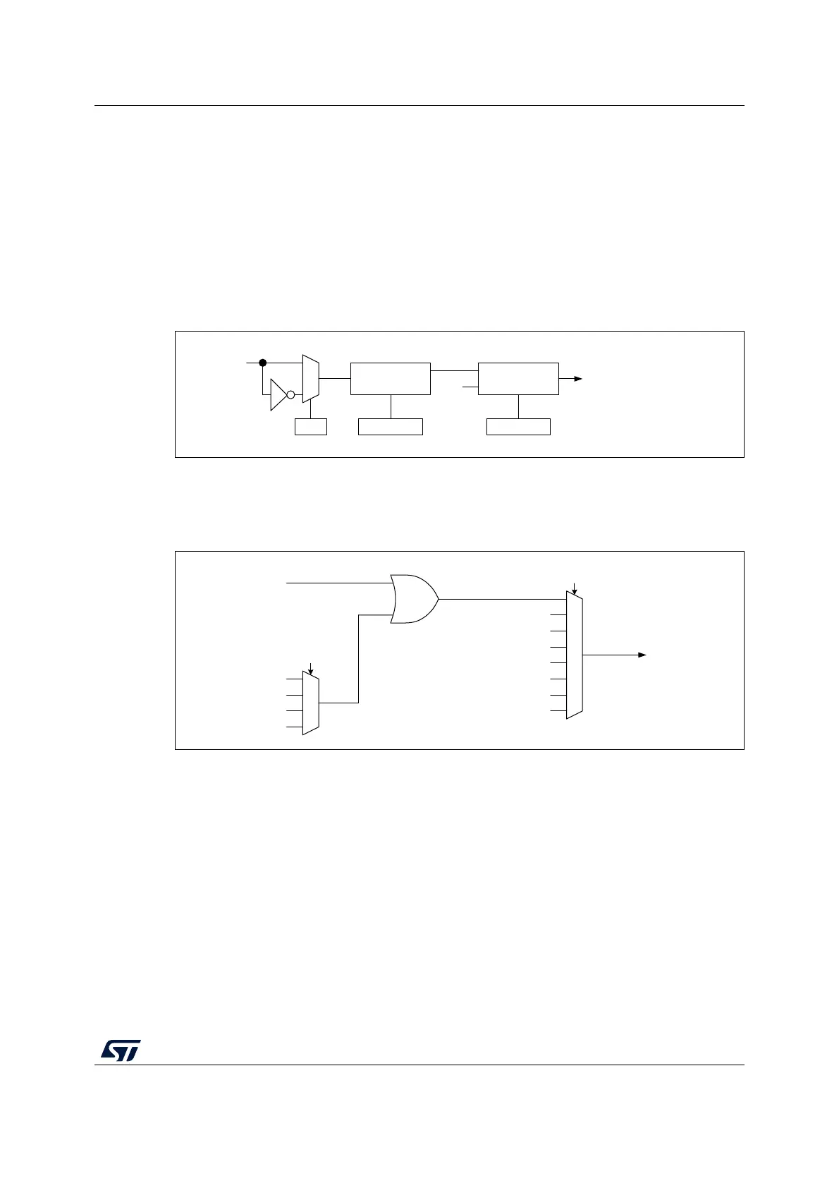
25.3.4 External trigger input
The timer features an external trigger input ETR. It can be used as:
• external clock (external clock mode 2, see Section 25.3.5)
• trigger for the slave mode (see Section 25.3.26)
• PWM reset input for cycle-by-cycle current regulation (see Section 25.3.7)
Figure 149 below describes the ETR input conditioning. The input polarity is defined with the
ETP bit in TIMxSMCR register. The trigger can be prescaled with the divider programmed
by the ETPS[1:0] bitfield and digitally filtered with the ETF[3:0] bitfield.
Figure 149. External trigger input block
The ETR input comes from multiple sources: input pins (default configuration), comparator
outputs and analog watchdogs. The selection is done with the ETRSEL[3:0] and the
TIM1_OR1[1:0] bitfields.
Figure 150. TIM1 ETR input circuitry
MS34403V2
To the Output mode controller
To the CK_PSC circuitry
To the Slave mode controller
0
1
ETR input
ETR
ETP
TIMx_SMCR
Divider
/1, /2, /4, /8
ETPS[1:0]
TIMx_SMCR
Filter
downcounter
ETF[3:0]
TIMx_SMCR
ETRP
f
DTS
MSv47460V2
ADC_AWD3
ADC_AWD2
ADC_AWD1
NC
TIM1_OR1[1:0]
ETR inputs from
AF controller
TIM1_AF1[17:14]
ETR legacy mode
COMP1
COMP2
NC
NC
NC
NC
NC
ETR input

 Loading...


