RM0453 Rev 1 559/1461
RM0453 Analog-to-digital converter (ADC)
592
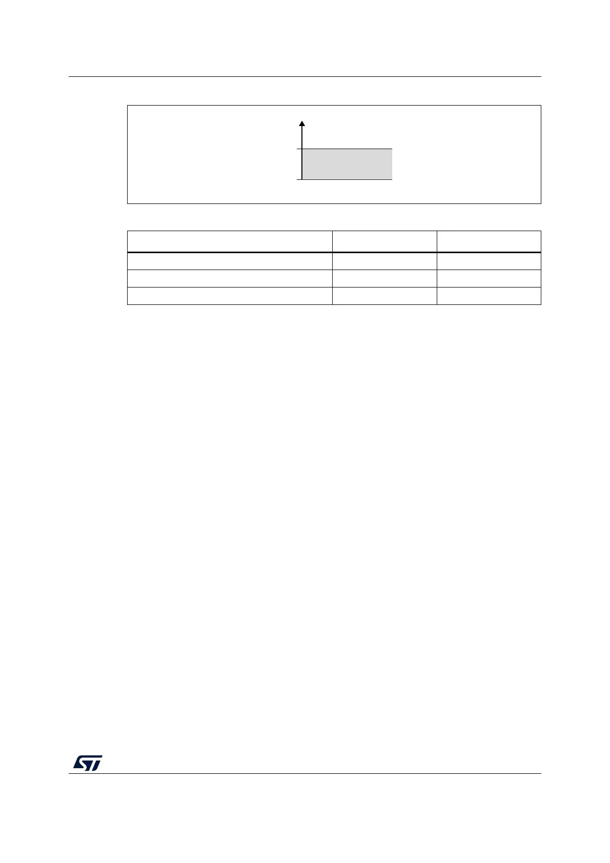
Figure 76. Analog watchdog guarded area
18.7.2 Description of analog watchdog 2 and 3
The second and third analog watchdogs are more flexible and can guard several selected
channels by programming the AWDxCHy in ADC_AWDxCR (x = 2, 3).
The corresponding watchdog is enabled when any AWDxCHy bit (x = 2,3) is set in
ADC_AWDxCR register.
When converting data with a resolution of less than 12 bits (configured through DRES[1:0]
bits), the LSB of the programmed thresholds must be kept cleared because the internal
comparison is always performed on the full 12-bit raw converted data (left aligned).
Table 106 describes how the comparison is performed for all the possible resolutions.
The AWD2/3 analog watchdog status bit is set if the analog voltage converted by the ADC is
below a low threshold or above a high threshold. These thresholds are programmed in
HTx[11:0] and LTx[11:0] of ADC_AWDxTR registers (x = 2 or 3). An interrupt can be
enabled by setting the AWDxIE bit in the ADC_IER register.
The AWD2 and ADW3 flags are cleared by software by programming them to 1.
18.7.3 ADC_AWDx_OUT output signal generation
Each analog watchdog is associated to an internal hardware signal, ADC_AWDx_OUT (x
being the watchdog number) that is directly connected to the ETR input (external trigger) of
some on-chip timers (refer to the timers section for details on how to select the
ADC_AWDx_OUT signal as ETR).
Table 107. Analog watchdog 1 channel selection
Channels guarded by the analog watchdog AWD1SGL bit AWD1EN bit
None x 0
All channels 0 1
Single
(1)
channel
1. Selected by the AWD1CH[4:0] bits
11
MS45396V1
Analog voltage
Higher threshold
Lower threshold
Guarded area
HTx
LTx

 Loading...


