Low-power timer (LPTIM) RM0453
962/1461 RM0453 Rev 1
The LPTIM output waveform can be configured through the WAVE bit as follow:
• Resetting the WAVE bit to ‘0’ forces the LPTIM to generate either a PWM waveform or
a One pulse waveform depending on which bit is set: CNTSTRT or SNGSTRT.
• Setting the WAVE bit to ‘1’ forces the LPTIM to generate a Set-once mode waveform.
The WAVPOL bit controls the LPTIM output polarity. The change takes effect immediately,
so the output default value changes immediately after the polarity is re-configured, even
before the timer is enabled.
Signals with frequencies up to the LPTIM clock frequency divided by 2 can be generated.
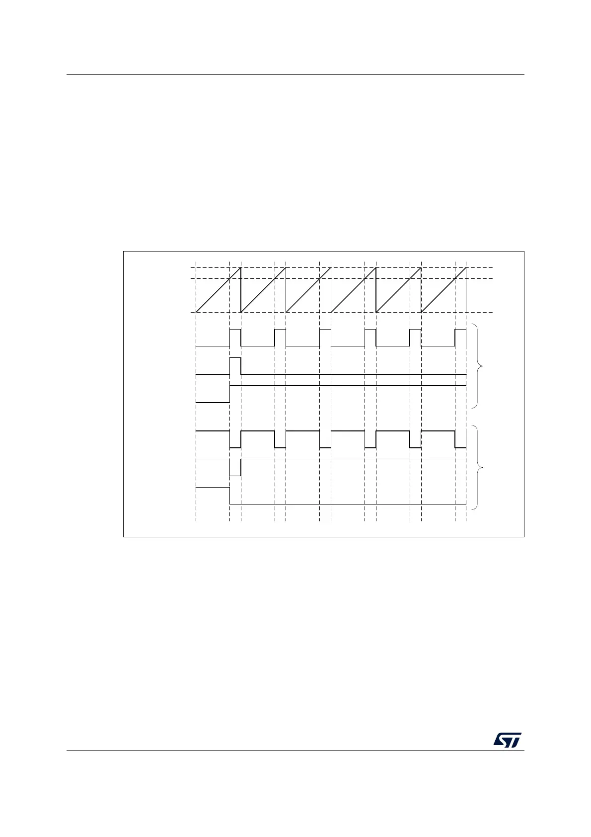
Figure 266 below shows the three possible waveforms that can be generated on the LPTIM
output. Also, it shows the effect of the polarity change using the WAVPOL bit.
Figure 266. Waveform generation
28.4.11 Register update
The LPTIM_ARR register and LPTIM_CMP register are updated immediately after the APB
bus write operation or in synchronization with the next LPTIM update event if the timer is
already started.
The PRELOAD bit controls how the LPTIM_ARR and the LPTIM_CMP registers are
updated:
• When the PRELOAD bit is reset to ‘0’, the LPTIM_ARR and the LPTIM_CMP registers
are immediately updated after any write access.
• When the PRELOAD bit is set to ‘1’, the LPTIM_ARR and the LPTIM_CMP registers
are updated at next LPTIM update event, if the timer has been already started.
MS32467V2
LPTIM_ARR
Compare
0
PWM
One shot
Set once
PWM
One shot
Set once
Pol = 0
Pol = 1

 Loading...


