CMS32L051 User Manual |Chapter 5 Universal Timer Unit (Timer4)
www.mcu.com.cn 123 / 703
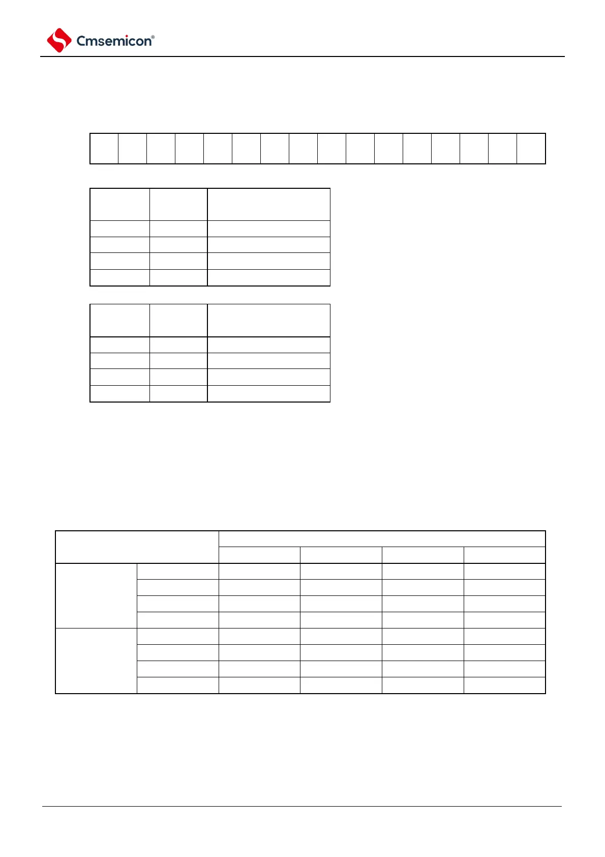
Figure 5-8 Format of the timer clock selection register m (TPSm)(2/2)
Symbol
15 14 13 12 11 10 9 8 7 6 5 4 3 2
1 0
TPSm
Note that in case of changing the clock selected as f
CLK
(changing the value of the system clock control register (CKC)),
the general-purpose timer unit (TTm=000FH) must be stopped. Even when selecting the operating clock (f
MCK
)
or the active edge of the input signal at the TImn pin, the general-purpose timer unit needs to be stopped.
Note: You must set bit15, 14, 11, and 10 to 0.
If you use channels 1 and 3 in 8-bit timer mode and use CKm2 and CKm3 as the operating clocks,
the interval times shown in the following table can be achieved through the interval timer function.
Table 5-3 Configurable interval for running clocks CKSm2 and CKSm3
Note: ○ contains an error of less than 5%.
Remark: 1. f
CLK
: The clock frequency of the CPU/peripheral hardware.
2. For details of the f
CLK
/2
r
waveform selected for the TPSm register, refer to 5.5.1 Counting Clock(f
TCLK
).