CMS32L051 User Manual |Chapter 5 Universal Timer Unit (Timer4)
www.mcu.com.cn 125 / 703
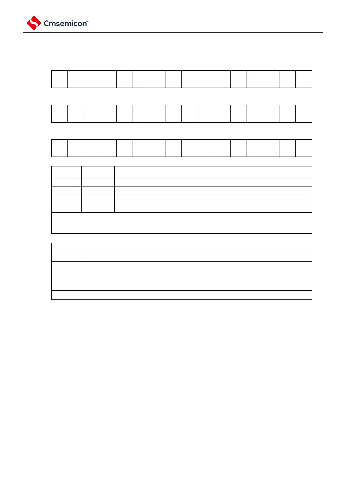
Figure 5-9 Table of timer mode register mns (TMRmn) (1/4)
Symbol
15 14 13 12 11 10 9 8 7 6 5 4 3 2 1 0
TMRmn
(n=2)
Symbol
15 14 13 12 11 10 9 8 7 6 5 4 3 2 1 0
TMRmn
(n=1, 3)
Symbol
15 14 13 12 11 10 9 8 7 6 5 4 3 2 1 0
TMRmn
(n=0)
Channel n running clock (f
MCK
) selection
The timer clock selects the operating clock CKm0 set by register m (TPSm).
The timer clock selects the operating clock CKm2 set by register m (TPSm).
The timer clock selects the operating clock CKm1 set by register m (TPSm).
The timer clock selects the operating clock CKm3 set by register m (TPSm).
The operating clock (f
MCK
) is used for edge detection circuitry. The sample clock and count clock
(f
TCLK)
are generated by setting the CCSmn bit. Only channels 1 and 3 have the option to run
clocks CKm2 and CKm3.
Channel n count clock (f
TCLK
) selection
The CKSmn0 bit and CKSmn1 bit specify the running clock (f
MCK
).
The active edge of the TImn pin input signal
0 in the case:
Channel 0: The effective edge of the input signal selected by TIOS0
Channel 1: The effective edge of the input signal selected by TIOS0
The count clock (f
TCLK)
is used for counters, output control circuitry, and interrupt control circuitry.
Note 1 bit11 is a read-only bit, fixed to 0, ignoring write operations.
Note 1 You must set bit13, 5, and 4 to 0.
2. When you want to change the clock selected as f
CLK
(change the value of the system clock control register (CKC)),
even if the CKSmn0 bit and the CKSmn1 bit specify the running clock (f) is selected
MCK
) or the active edge of the
input signal at the TImn pin as the count clock (f
TCLK),
the timer array unit must also be stopped TTm=00FFH).
Note m: Unit number (m=0, 1) n: channel number (n=0~3).