CMS32L051 User Manual |Chapter 5 Universal Timer Unit (Timer4)
www.mcu.com.cn 126 / 703
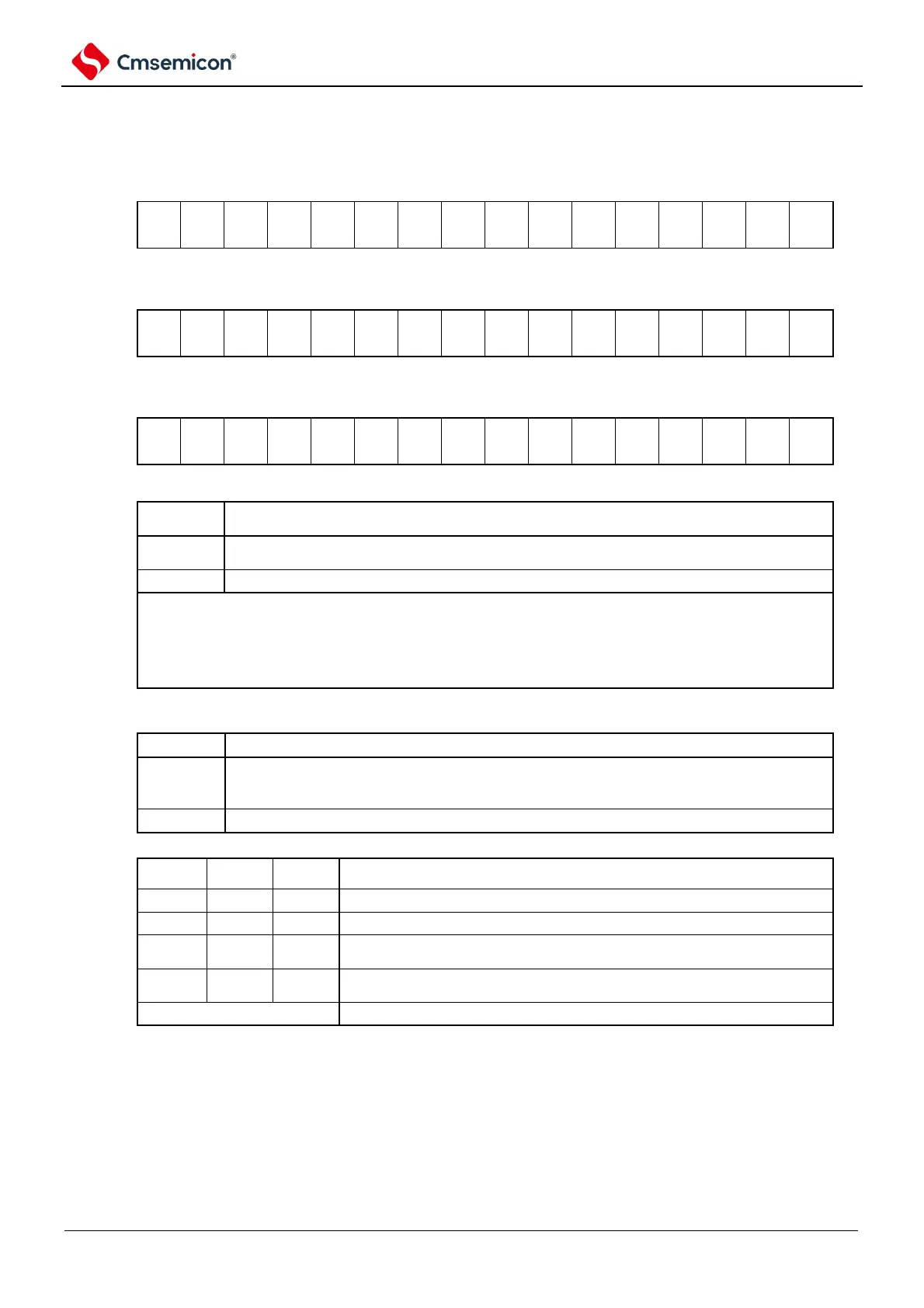
Figure 5-10 Table of timer mode register mns (TMRmn) (2/4)
Symbol
15 14 13 12 11 10 9 8 7 6 5 4 3 2 1
0
TMRmn
(n=2)
Symbol
15 14 13 12 11 10 9 8 7 6 5 4 3 2 1
0
TMRmn
(n=1, 3)
Symbol
15 14 13 12 11 10 9 8 7 6 5 4 3 2 1
0
TMRmn
(n=0)
(bit11 of TMRmn(n=2))
Choice of independent channel operation / multi-channel linkage operation (slave or master) of
channel n
It is used as a slave channel for independent channel operation function or multi-channel linkage
operation function.
It is used as the main control channel for multi-channel linkage operation function.
Only channel 2 can be set as the main control channel (MASTERmn=1).
Channel 0 is fixed to 0 (because channel 0 is the channel at the highest bit, it is
independent of the setting of this bit and is used as the master channel).
For channels used as stand-alone channel operating functions, place the MASTERmn
position 0.
Choice of 8-bit timer/16-bit timer operation for channel 1 and channel 3
Used as a 16-bit timer.
(Used as a slave channel for independent channel operation function or multi-channel linkage
operation function)
Setting of the start trigger and the capture trigger of channel n
Only software triggers start to be valid (no other trigger source is selected).
Use the active edge of the TImn pin input for start trigger and snap trigger.
Use the bilateral edges of the TImn pin inputs for start triggering and snap
triggering, respectively.
The interrupt signal of the master channel is used (in the case of slave
channels with multi-channel linkage operation function).
Note 1: bit11 is a read-only bit, fixed to 0, ignoring write operations.
Remark: m: unit number (m=0,1) n: channel number (n=0~3).