CMS32L051 User Manual |Chapter 5 Universal Timer Unit (Timer4)
www.mcu.com.cn 128 / 703
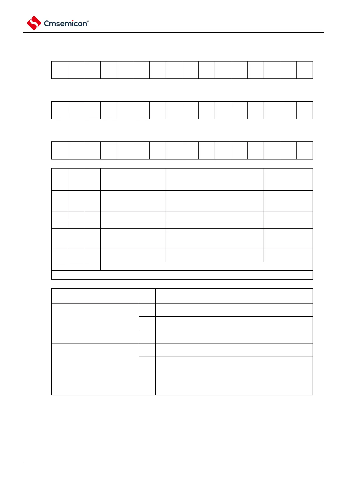
Figure 5-12 Table of timer mode register mns (TMRmn) (4/4)
Symbol
15 14 13 12 11 10 9 8 7 6 5 4 3 2 1
0
TMRmn
(n=2)
Symbol
15 14 13 12 11 10 9 8 7 6 5 4 3 2 1
0
TMRmn
(n=1, 3)
Symbol
15 14 13 12 11 10 9 8 7 6 5 4 3 2 1
0
TMRmn
(n=0)
The setting of the
channel n operating
mode
Interval timer/square wave output/
Crossover function / PWM output
(master).
Measurement of input pulse intervals
Delay counter/single trigger pulse
output/PWM output
(Subgenerated)
Capture & Single Count
Mode
Measurement of the high and low level
width of the input signal
The operation of each mode varies depending on the MDmn0 bit (refer to the table below).
Operating mode (MDmn3~MDmn1
bit setting (see table above)).
Start counting and interrupt settings
Interval timer mode (0, 0, 0)
Capture mode (0, 1, 0).
No timer interrupt occurs at the start of the count (nor does the
output of the timer change).
A timer interrupt is generated at the start of the count (the output of
the timer also changes).
Event counter patterns (0, 1, 1).
No timer interrupt occurs at the start of the count (nor does the
output of the timer change).
Single count mode
Note 2
(1, 0, 0)
The start trigger in the count run is invalid. No interruption occurs
at this time.
The start of the count run triggers a valid
Note
3
. No interruption
occurs at this time.
Capture & Single Count Mode (1,
1, 0).
No timer interrupt occurs at the start of the count (nor does the
output of the timer change). The start trigger in the count run is
invalid.
No interruption occurs at this time.
Note 1: bit11 is a read-only bit, fixed to 0, ignoring write operations.
2. In single-count mode, the interrupt output (INTTMmn) and TOmn output at start count are not controlled.
3. If a start trigger is generated during operation (TSmn=1), the counter is initialized and the count is restarted (no
interrupt request is generated).
Remark: m: unit number (m=0,1) n: channel number (n=0~3).