CMS32L051 User Manual |Chapter 5 Universal Timer Unit (Timer4)
www.mcu.com.cn 151 / 703
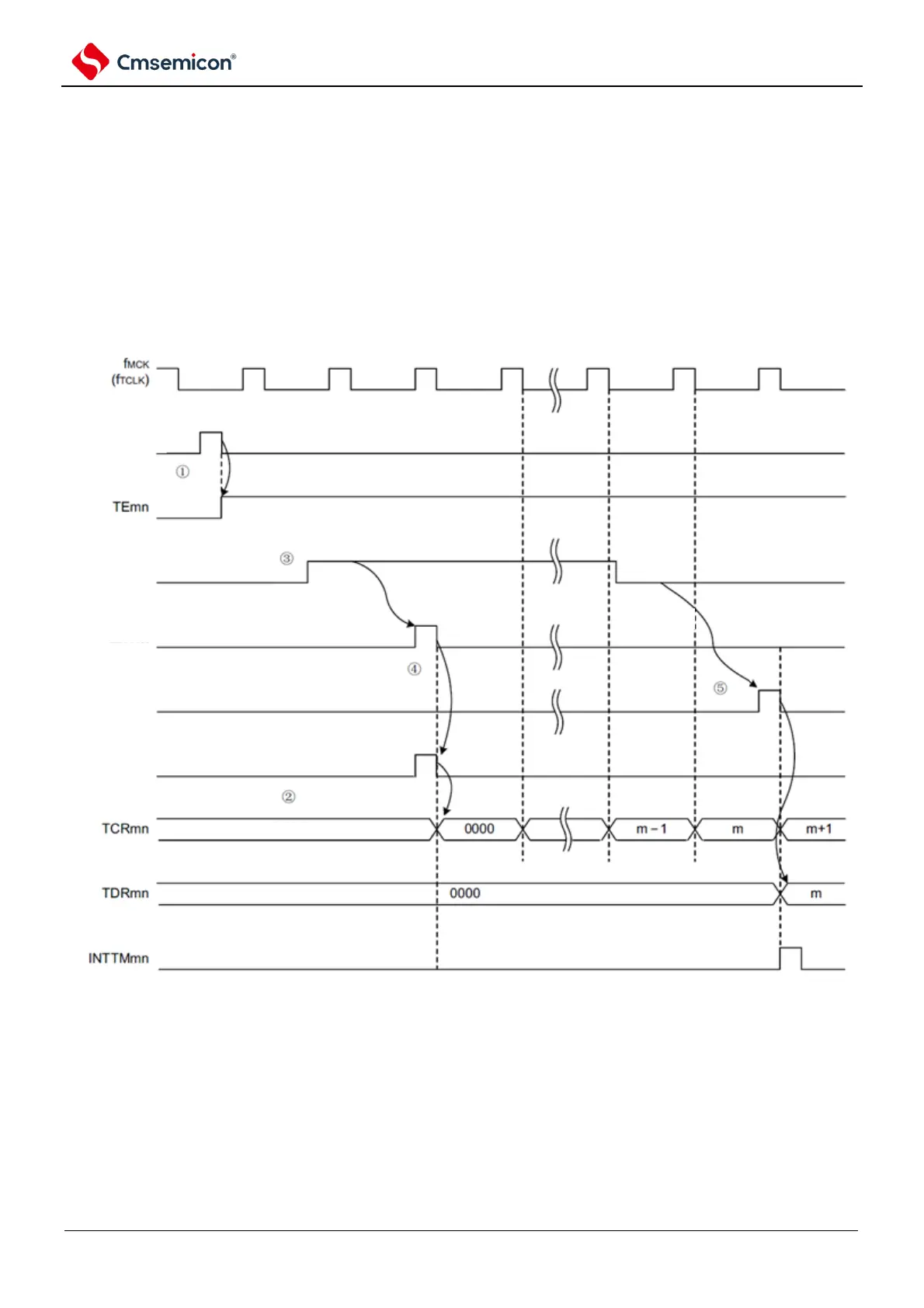
(5) Capture & single count mode operation (measurement of high-level width)
(1) The TSmn bit of the start register m (TSm) is written 1 through the given timer channel to
enter the operating enable state (TEmn=1).
(2) The timer count register mn (TCRmn) holds the initial value until a start trigger signal is
generated.
(3) Detect the rising edge of TImn input.
(4) After the start trigger signal is generated, 0000H is loaded into the TCRmn register and the
count begins.
(5) If the falling edge of the TImn input is detected, the value of the TCRmn register is captured to
the TDRmn register, and an INTTMmn interrupt is generated.
Figure 5-30 Operation timing (capture & single count mode: measurement of high-level width)
Note This is the timing when no noise filter is used. If a noise filter is used, edge detection is delayed by 2 more f
MCK
cycles from the TImn input (3~4 cycles in total). The 1 cycle error is because the TImn input and counting clock (f
MCK
) are
not synchronized.