CMS32L051 User Manual |Chapter 5 Universal Timer Unit (Timer4)
www.mcu.com.cn 156 / 703
(3) TOmn pin change regarding slave channel output mode (TOMmn=1)
(a) When the setting of the timer output level register m (TOLm) is changed during timer operation
If you change the setting of the TOLm register while the timer is running, the setting is valid when the
TOmn pin change condition is generated. The output level of the TOmn pin cannot be changed by rewriting
the TOLm register.
When the TOMmn bit is 1, the operation when changing the value of the TOLm register in timer operation
(TEmn=1) is shown below.
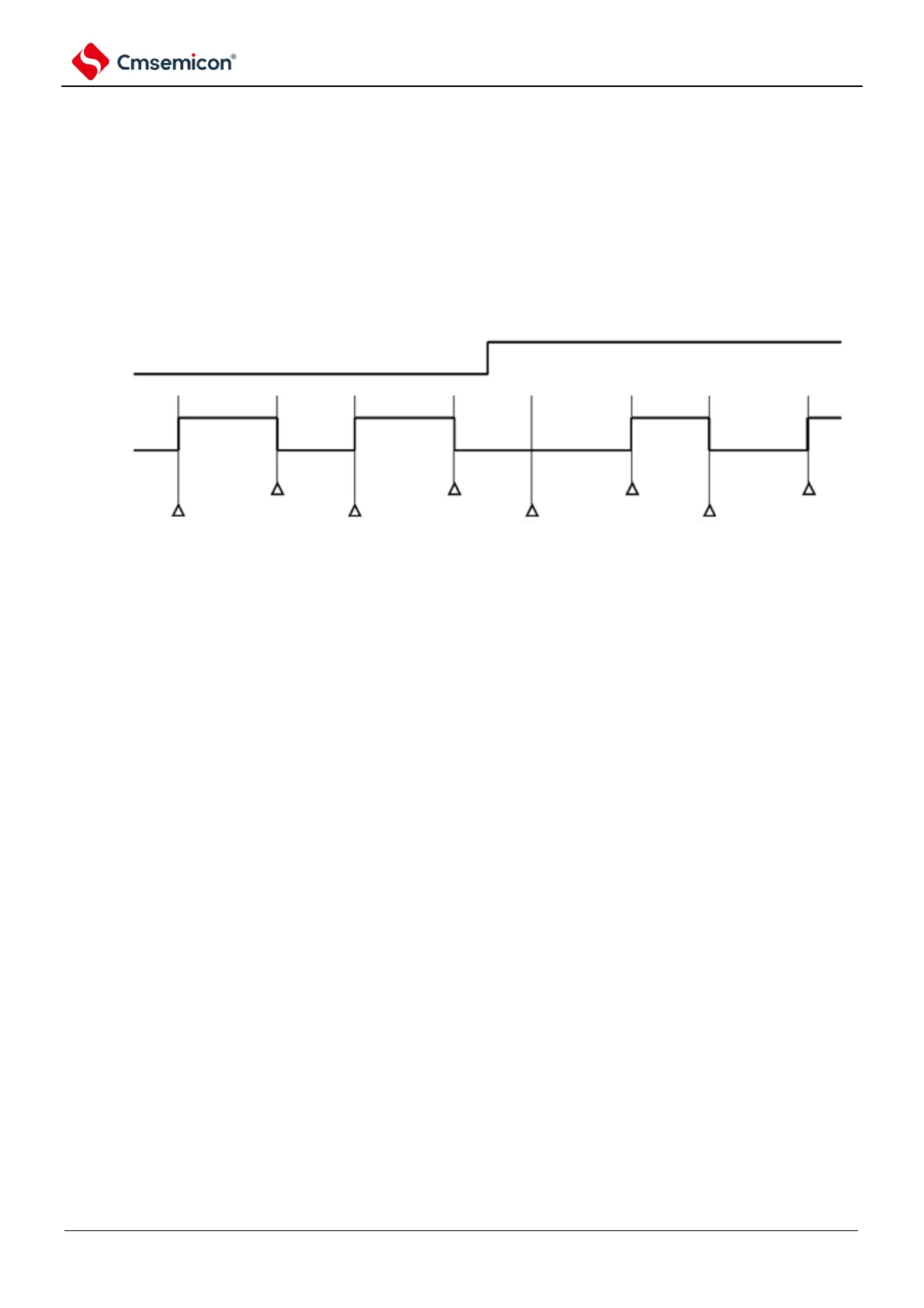
Figure 5-35 Operation when the contents of the TOLm register are changed during timer operation
Note 1. Set: The output signal of the TOmn pin changes from an invalid level to an valid level.
Reset: The output signal of the TOmn pin changes from a valid level to an invalid level.
2. m: unit number (m=0, 1) n: channel number (n=0~3).
(b) Set/reset timing
To achieve 0% and 100% output at PWM output, the TOmn pin/TOmn at the time of the master
channel timer interrupt (INTTMmn) is generated through the slave channel. The timing delay of the bits
is 1 count clock.
When the set condition and the reset condition arise at the same time, the reset condition takes
precedence.
The set/reset operation status when setting the master/slave channel according to the following
method is shown in Figure 5-35.
Master channel: TOEmn=1, TOMmn=0, TOLmn=0
Slave channel: TOEmp=1, TOMmp=1, TOLmp=0