CMS32L051 User Manual |Chapter 5 Universal Timer Unit (Timer4)
www.mcu.com.cn 164 / 703
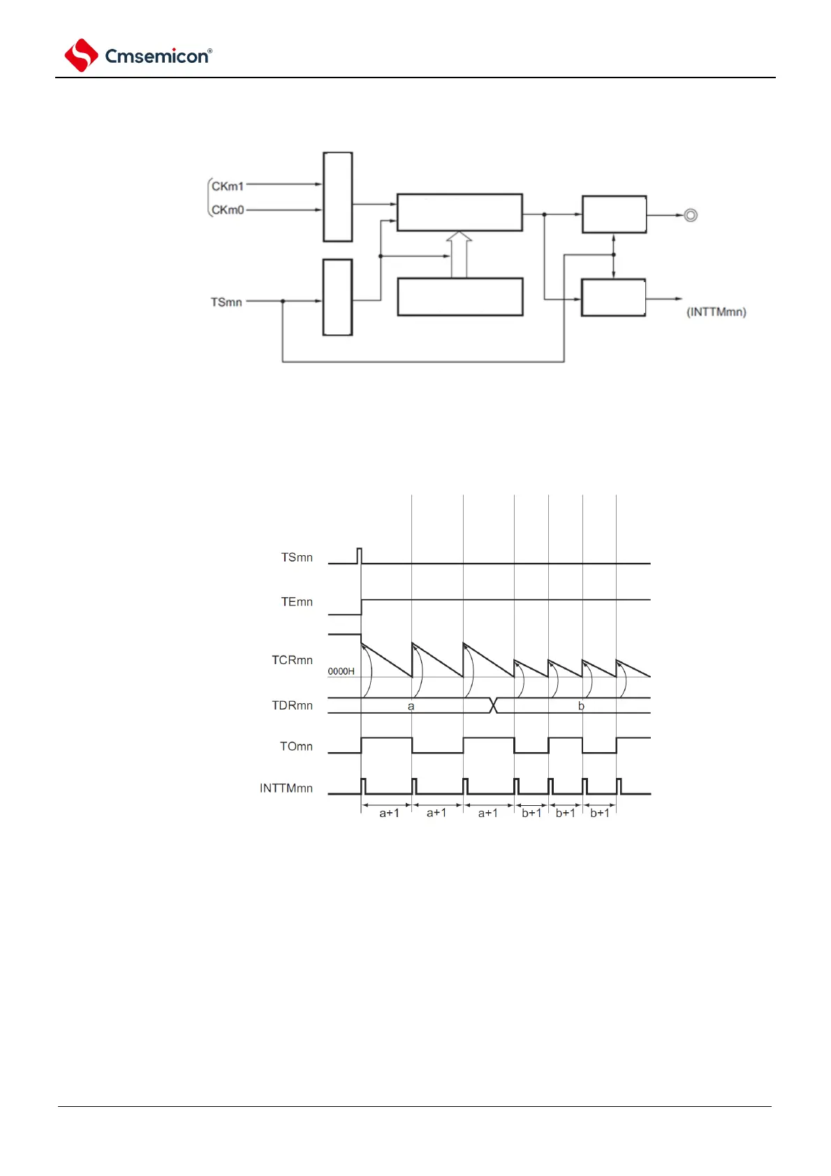
Figure 5-42 Basic timing example of operation as a spacer timer / square wave output (MDmn0=1)
Note: On channels 1 and 3, clocks can be selected from CKm0, CKm1, CKm2, and CKm3.
Figure 5-43 Basic timing example of operation as a spacer timer / square wave output (MDmn0=1)
Note 1. m: unit number (m= 0,1) n: channel number (n=0 ~ 3).
2. TSmn: bit n of timer channel start register m (TSm).
TEmn: timer channel enable bit n of status register m (TEm).
TCRmn: timer count register mn (TCRmn).
TDRmn: timer data register mn (TDRmn).
TOmn: TOmn pin output signal.