CMS32L051 User Manual |Chapter 11 A/D Converter
www.mcu.com.cn 270 / 703
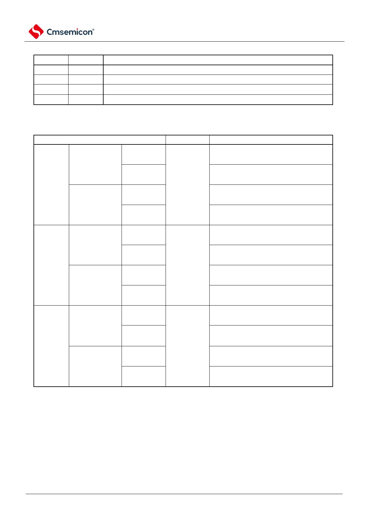
Table11-1 Configuration of ADCS and ADCE bits
Table11-2 Setting and clearing conditions for ADCS bits
Continuous
conversion
mode
When giving
ADCS bits to
write
1 time
When writing 0 to the ADCS bit
writing 0 to the ADCS bit
Automatically clear 0 at the end of A/D
conversion.
Continuous
conversion
mode
When writing 0 to the ADCS bit
0 to the ADCS bit
4 channels are converted at the
end, the 0 is automatically cleared.
Hardware
trigger no-
wait mode
Continuous
conversion
mode
When giving
ADCS bits to
write
1 time
When writing 0 to the ADCS bit
writing 0 to the ADCS bit
Continuous
conversion
mode
When writing 0 to the ADCS bit
0 to the ADCS bit
Hardware
trigger wait
mode
Continuous
conversion
mode
When the input
hardware
triggers
When writing 0 to the ADCS bit
0 to the ADCS bit
Automatically clear 0 at the end of A/D
conversion.
Continuous
conversion
mode
When writing 0 to the ADCS bit
0 to the ADCS bit
4 channels are converted at the
end, the 0 is automatically cleared.