EasyManua.ls Logo

Cmsemicon CMS32L051 - Page 35

Default Icon
703 pages
Print Icon
To Next Page IconTo Next Page
To Previous Page IconTo Previous Page
Loading...
V1.2.2
CMS32L051 User Manual |Chapter 2 Pin Function
www.mcu.com.cn 35 / 703
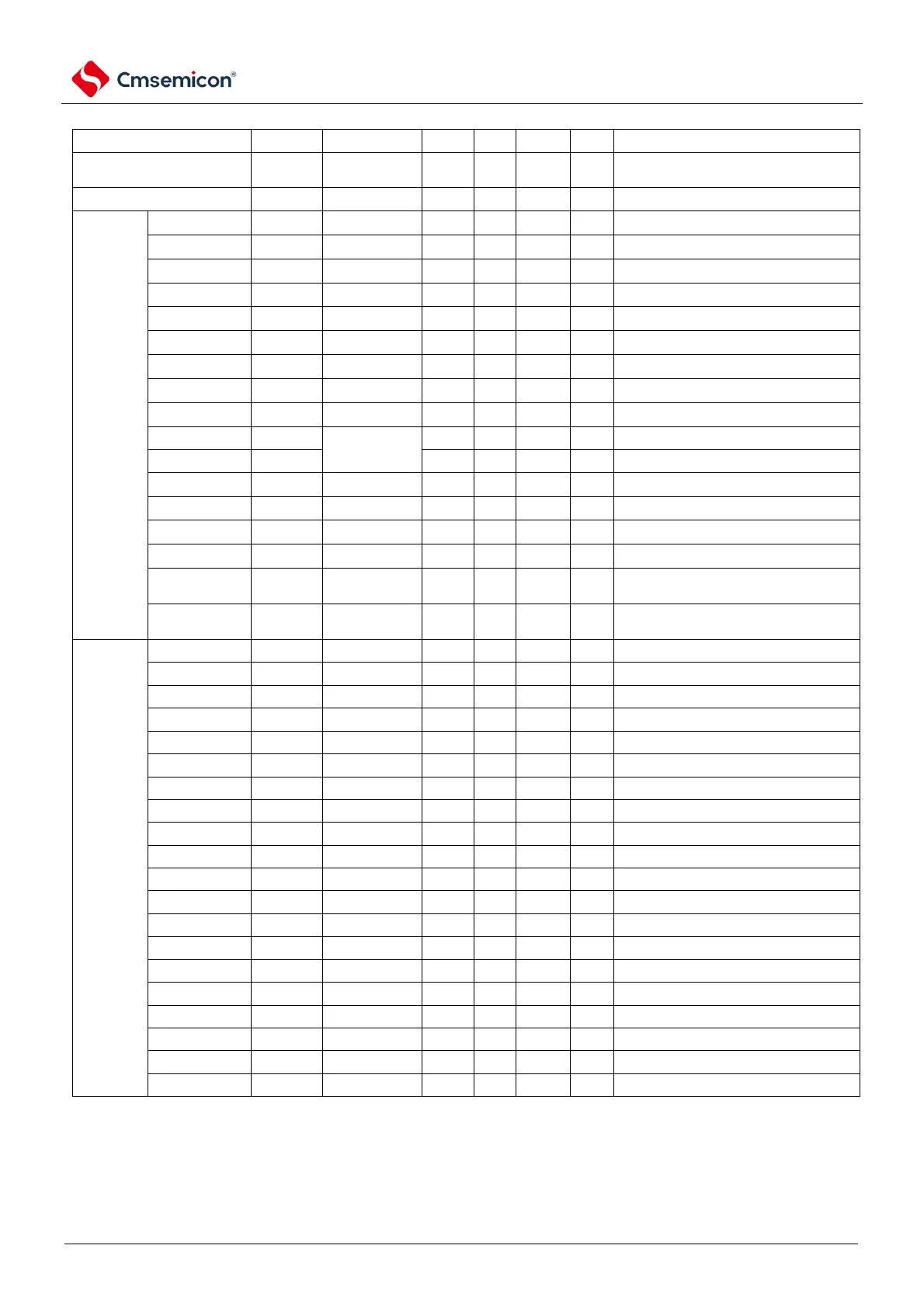
Table 2-3 Configuration method of concurrent input function
Function name
Input/output
xxxPCFP[5:0]
PMCxx
PMxx
POMxx
Pxx
Remark
Simulation function
Input/output
x
1
x
×
×
All analog functions are directed to fixed ports only
and are not configurable, Refer to the data sheets
for each product family
GPIO
input
x
0
1
×
×
Concurrent
inputs that
can be
mapped
arbitrarily
TI10
input
Configure the
TI10PCFG
0
1
×
×
Can be mapped to any port
TI11
input
Configure the
TI11PCFG
0
1
×
×
Can be mapped to any port
TI12
input
Configure the
TI12PCFG
0
1
×
×
Can be mapped to any port
TI13
input
Configure the
TI13PCFG
0
1
×
×
Can be mapped to any port
INTP0
input
Configure
INTP0PCFG
0
1
×
×
By default, P136 is used and can be mapped to
any port
INTP1
input
Configure
INTP1PCFG
0
1
×
×
P50 is used by default and can be mapped to any
port
INTP2
input
Configure
INTP2PCFG
0
1
×
×
P51 is used by default and can be mapped to any
port
INTP3
input
Configure
INTP3PCFG
0
1
×
×
P30 is used by default and can be mapped to any
port
SCLKI00
input
Configure
SCLKI00PCFG
0
1
×
×
Can be mapped to any port
SDI00/RxD0
input
Configure
SDI00PCFG
0
1
×
×
Can be mapped to any port
SDA00
bidirectional
0
0
1
1
Can be mapped to any port, except P121 to P124
SS00
input
Configure
SS00PCFG
0
1
×
×
Can be mapped to any port
RxD1
input
Configure the
RXD1PCFG
0
1
×
×
Can be mapped to any port
SCLKI20
input
Configure
SCLKI20PCFG
0
1
×
×
Can be mapped to any port
SDI20/RxD2/IrRXD
input
Configure the
SDI20PCFG
0
1
×
×
Can be mapped to any port
SCLA0
bidirectional
Configure
SCLA0PCFG
0
0
1*
0
It can be mapped to any port, except for
P121~P124POMxx automatic setting 1, no
software configuration is required
SDAA0
bidirectional
Configure
SDAA0PCFG
0
0
1*
0
It can be mapped to any port, except for
P121~P124POMxx automatic setting 1, no
software configuration is required
Concurrent
input
mapped to a
fixed port
TI00
input
x
0
1
×
×
Fixed use P00
TI01
input
x
0
1
×
×
Fixed use P16
TI02
input
x
0
1
×
×
Fixed use P17
TI03
input
x
0
1
×
×
Fixed use P31
SCLKI01
input
x
0
1
×
×
Fixed use P75
SDI01
input
x
0
1
×
×
Fixed use P74
SDA01
bidirectional
x
0
0
1
1
Fixed use P74
SCLKI11
input
x
0
1
×
×
Fixed use P10
SDI11
input
x
0
1
×
×
Fixed use P11
SDA11
bidirectional
x
0
0
1
1
Fixed use P11
SDA20
bidirectional
x
0
0
1
1
Fixed use P14
SCLKI21
input
x
0
1
×
×
Fixed use P70
SDI21
input
x
0
1
×
×
Fixed use P71
SDA21
bidirectional
x
0
0
1
1
Fixed use P71
KR0
input
x
0
1
×
×
Fixed use P70
KR1
input
x
0
1
×
×
Fixed use P71
KR2
input
x
0
1
×
×
Fixed use P72
KR3
input
x
0
1
×
×
Fixed use P73
KR4
input
x
0
1
×
×
Fixed use P74
KR5
input
x
0
1
×
×
Fixed use P75
Note: The data port (SDAxx) of the easy IIC, the clock port of the IICA (SCLA0) and the data port of the IICA (SDAA0) are two-way
communication, and only SDI00PCFG, SCLA0PCFG, SDAA0PCFG, and PxxCFG need to be configured when used. And the port
output latch Pxx needs to be set to the appropriate value, the configuration method is detailed in the above table, for reasons please
refer to 2.5.1 Basic idea when using the multiplexed output feature.

Table of Contents

Related product manuals