CMS32L051 User Manual |Chapter 12 Universal Serial Communication Unit
www.mcu.com.cn 401 / 703
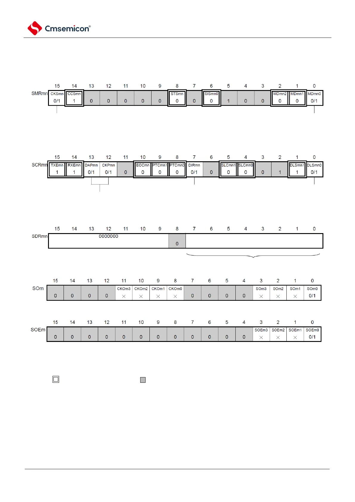
(1) Register setting
Figure 12-87 Slave select input function (SSPI00) Example of register setting content when slave send and
receive (1/2)
(a) serial mode register mn (SMRmn)
(b) serial communication operation configuration registermn mn(SCRmn)
(c) serial data regsiter mn (SDRmn) (low 8 bit: SIOp)
(d) serial output register m(SOm) ...Only configure bit of target channel
(e) serial output enable registerm (SOEm)only set bit of target channel to 1.
channel n operational clock (fMCK)
0: SPSm register configured pre-scaler output clock CKm0
1: SPSm register configured pre-scaler output clock CKm1
interrupt source of channel n
0: Transmit completion interrupt
1: Buffer empty interrupt
data transmit sequence selection
0: perform MSB first input/output
1: perform LSB first input/output
data length configuration
0: 7 bit data length
1: 8 bit data length
data and clock phase selection (details refer to "19.3
control universal serial communication unit registers)
SIOp
baud rate configuration
configuration of transmit data/received data register
Note Data must be sent to the SIOp register settings before the master device starts the output clock.
Notice 1.m: Unit number (m=0)n: Channel number (n=0)p:SSPI number (p=00)
2. : Fixed in Slave Receive mode. : Cannot be set (initial value).
×: This is the bit that cannot be used in this mode (set the initial value if it is not used in other modes either).
0/1: Set 0 or 1 according to the user's purpose.