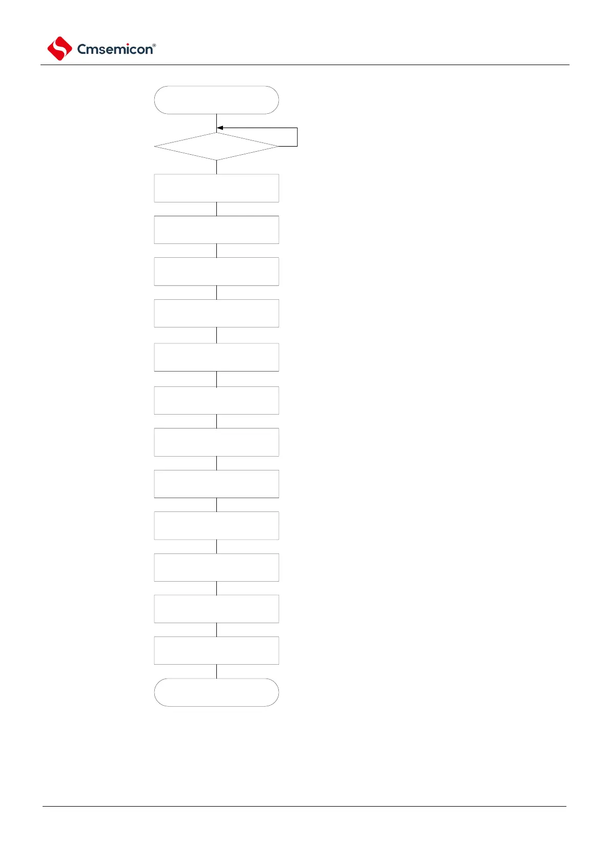
restart configuration starts.
master device preparation
complete?
port operation
modify SPSm register
configuration
Yes
No
wait till commuication target (master device)
stops or communication ends
via Configure port register and port mode
register, set clock output of target channel to
invalid.
re-configure when modifing operational clock
configuration
re-configure when serial mode register mn.
re-configure when serial communication
operation configuration register mn.
modify SMRmn register
configuration
modify SCRmn register
configuration
modify SOEm register
configuration
modify SOm register
configuration
modify SOEm register
configuration
port operation
write into SSm register
via Configure port register and port mode
register, data output of target channel set to
valid. When connecting to multiple slave devices,
configure N-channel open drain before configure
data output.
set SSmn bit of target channel to "1"
(SEmn=1, configure to enable operation
state).
restart configuration completes.
set SOEmn bit to "0", stop output of target
channel
configure serial data (Somn) initial output voltage
set SOEmn bit to 1, enable target channel data
otuput
clear error flag
when OVF flag remains at set state, erase via
serail flag clear trigger register mn(SIRmn).
start communication
configure transmit data to SIOp register(bit 7~0 of
register SDRmn), wait for master device clock.
write into ISC register
set SSIE00 bit to 1, enable channel 0
slave selection function operates.
(mandatory)
(mandatory)
(selection)
(selection)
(selection)
(selection)
(selection)
(selection)
(mandatory)
(selection)
(mandatory)
(mandatory)
(mandatory)
Note 1 Before the master device starts to output the clock, data must be sent to the SIOp register settings.
2. If you override PER0 in the abort setting to stop the clock, you must wait until the communication object (the
master device) stops or the communication is over to make the initial setting instead of starting the setting again.