CMS32L051 User Manual |Chapter 12 Universal Serial Communication Unit
www.mcu.com.cn 414 / 703
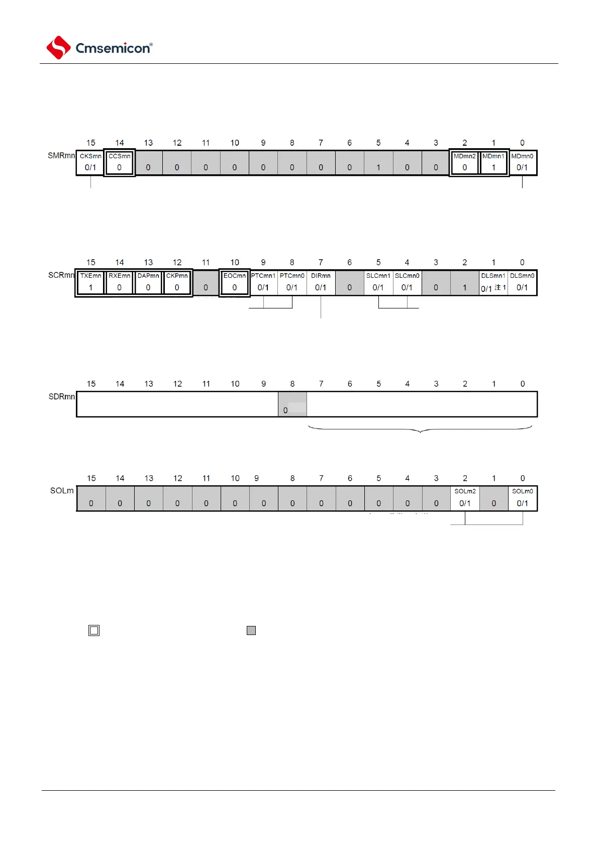
(1) Register setting
Figure 12-96 Example of register settings when UART is sent by UART (UART0~UART 2) (1/2)
(a) serial mode register mn (SMRmn)
(b) serial communication operation configuration register mn (SCRmn)
(c) serial data regsiter mn (SDRmn) (low 8 bit:TXDq)
(d) serial output voltage register m (SOLm) Only configure bit of target channel.
channel n operational clock (fMCK)
0: SPSm register configured pre-scaler output clock CKm0
1: SPSm register configured pre-scaler output clock CKm1
channel n interrupt source
0: Transmit completion interrupt
1: Buffer empty interrupt
data transmit sequence selection
0: perform MSB first input/output
1: perform LSB first input/output
stop bit configuration
01B: add 1 bit
10B: add 2 bits
parity check bit configuration
00B: no parity check
01B: add zero parity
10B: add even parity
11B: add odd parity
TXDq
0: positive phase (normal) transmit
1: inverted phase transmit
baud rate configuration transmit data configuration
Note2
Note 1 Limited to SCR00 registers, other fixed as 1.
2. When communicating with a length of 9 bits of data, bit0 to 8 of the SDRm0 register is the setting area for sending
data. Only UART0 can communicate with 9-bit data lengths.
Note 1.m: Unit number (m=0, 1) n: Channel number (n=0, 2)q: UART numbers (q=0~2)mn=00, 02, 10
2. : Fixed in UART send mode. : Cannot be set (initial value).
×: This is the bit that cannot be used in this mode (set the initial value if it is not used in other modes either).
0/1: Set 0 or 1 according to the user's purpose.