CMS32L051 User Manual |Chapter 12 Universal Serial Communication Unit
www.mcu.com.cn 415 / 703
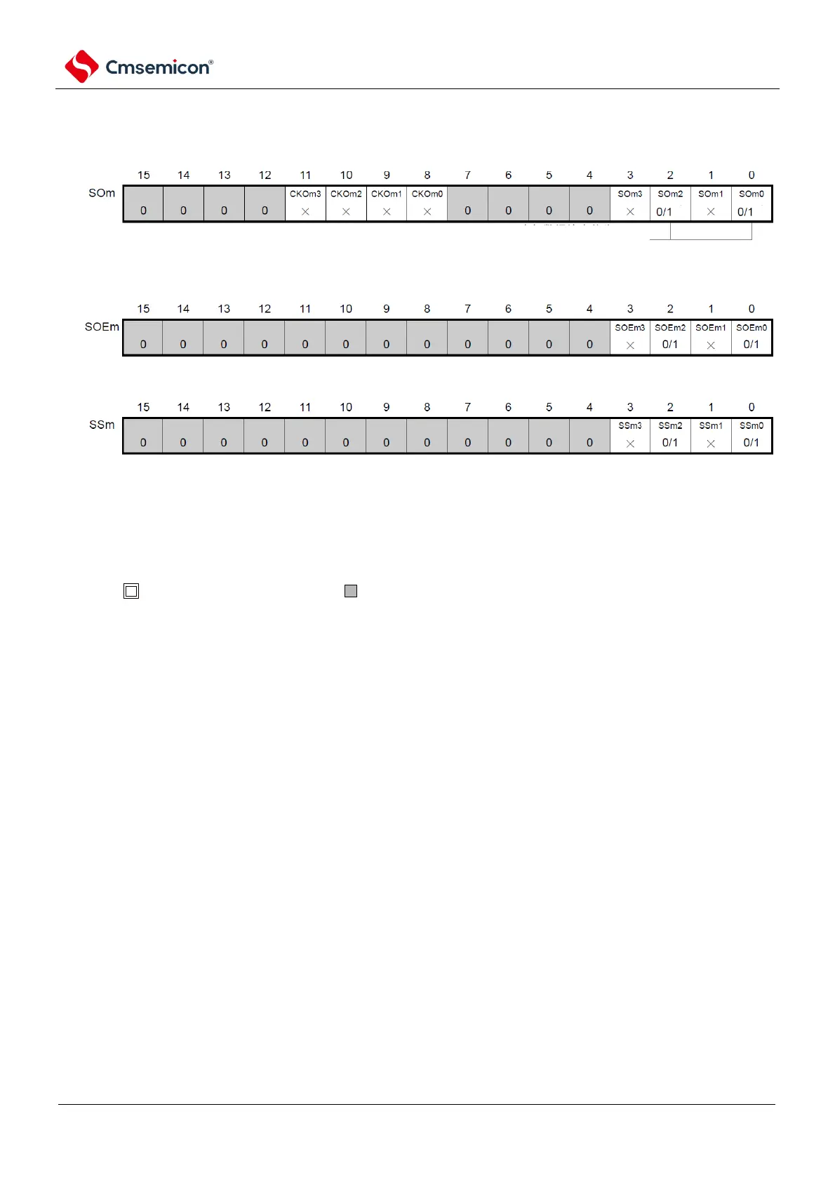
Figure 12-96 Example of register settings when UART is sent by UART (UART0~UART 2) (2/2)
(f) serial output enable register m (SOEm)Only set bit of target channel to "1".
(e) serial output register m (SOm)Only configure bit of target channel
(g) serial channel start register m (SSm) Only set bit of target channel to "1".
0: serial data output value as "0"
1: serial data output value as "1"
Note Note
Note that before starting to send, when the SOLmn bit of the corresponding channel is 0, it must be set to 1;
When the SOLmn bit of the corresponding channel is 1, 0 must be set. During communication, the value
varies from data to communication.
Note 1.m: Unit number (m=0, 1) n: Channel number (n=0, 2)q: UART numbers (q=0~2)mn=00, 02, 10
2. : Fixed in UART send mode. : Cannot be set (initial value).
×: This is the bit that cannot be used in this mode (set the initial value if it is not used in other modes either).
0/1: Set 0 or 1 according to the user's purpose.