CMS32L051 User Manual |Chapter 20 Standby Function
www.mcu.com.cn 630 / 703
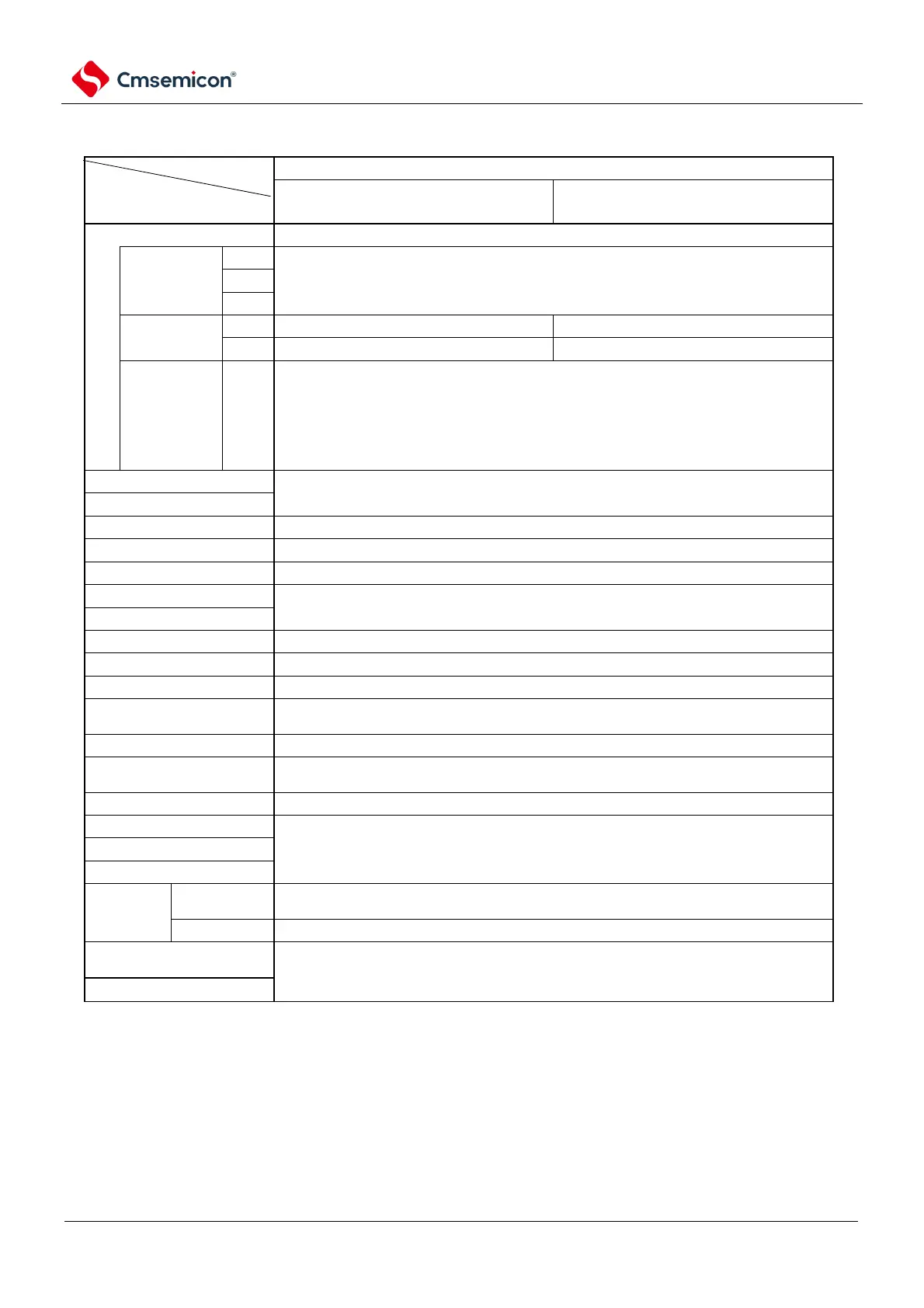
Table 20-1 Operation status in sleep mode (2/2)
Setting of the sleep mode
Item
Execution of WFI instructions while the CPU is running at the subsystem clock
CPU running at XT1 clock (F
XT
)
CPU running on external subsystem
clock (F
EXS
)
Stop supplying clocks to the CPU.
Continue to run (cannot be stopped).
Continue to run (cannot be stopped).
Low-speed
internal
oscillation
Clock of the
device
Mode control registers (OSMC) are provided via bit0 (WDSTBYON) and bit4 (WDTON) of
option bytes (000C0H) and the subsystem clock WUTMMCK0 bit is set.
WUTMMCK0=1: Oscillation
WUTMMCK0=0 and WDTON=0: Stop
WUTMMCK0=0, WDTON=1 and WDSTBYON=1: Oscillation
WUTMMCK0=0, WDTON=1 and WDSTBYON=0: Stop
Stop running (can run when DMA is executed).
Remains in the state it was in before it was set to sleep mode.
When RTCLPC=0, it can run (otherwise it is disabled).
See Chapter 10: The Watchdog Timer.
Clock output/buzzer output
When RTCLPC=0, it can run (otherwise it is disabled).
Universal Serial
Communication Unit (SCI)
When RTCLPC=0, it can run (otherwise it is disabled).
Data Transfer Controller
(DMA).
When RTCLPC=0, it can run (otherwise it is disabled).
Links can be made between runnable function blocks.
Voltage detection function
When DMA is executed in the operation of the RAM area, it can be run.
RAM parity error detection
function
It can run when performing DMA.
Note Stop running: Automatically stops running when transferred to sleep mode.
Disable Run: Stop running before moving to sleep mode.
f
IH: High Speed Internal Oscillator Clock fIL: Low Speed Internal Oscillator Clock
fX: X1 clock fEX: External master system clock
fXT: XT1 clock fEXS: External subsystem clock