USB on-the-go full-speed/high-speed (OTG_FS/OTG_HS) RM0390
1084/1328 RM0390 Rev 4
31.4.3 OTG core
The USB OTG receives the 48 MHz clock from the reset and clock controller (RCC). The
USB clock is used for driving the 48 MHz domain at full-speed (12 Mbit/s) and must be
enabled prior to configuring the OTG core.
The CPU reads and writes from/to the OTG core registers through the AHB peripheral bus.
It is informed of USB events through the single USB OTG interrupt line described in
Section 31.13: OTG_FS/OTG_HS interrupts.
The CPU submits data over the USB by writing 32-bit words to dedicated OTG locations
(push registers). The data are then automatically stored into Tx-data FIFOs configured
within the USB data RAM. There is one Tx FIFO push register for each in-endpoint
(peripheral mode) or out-channel (host mode).
The CPU receives the data from the USB by reading 32-bit words from dedicated OTG
addresses (pop registers). The data are then automatically retrieved from a shared Rx FIFO
configured within the 1.25[FS] / 4[HS]-Kbyte USB data RAM. There is one Rx FIFO pop
register for each out-endpoint or in-channel.
The USB protocol layer is driven by the serial interface engine (SIE) and serialized over the
USB by the transceiver module within the on-chip physical layer (PHY) or external HS PHY.
31.4.4 Full-speed OTG PHY
(a)
The embedded full-speed OTG PHY is controlled by the OTG FS core and conveys USB
control & data signals through the full-speed subset of the UTMI+ Bus (UTMIFS). It provides
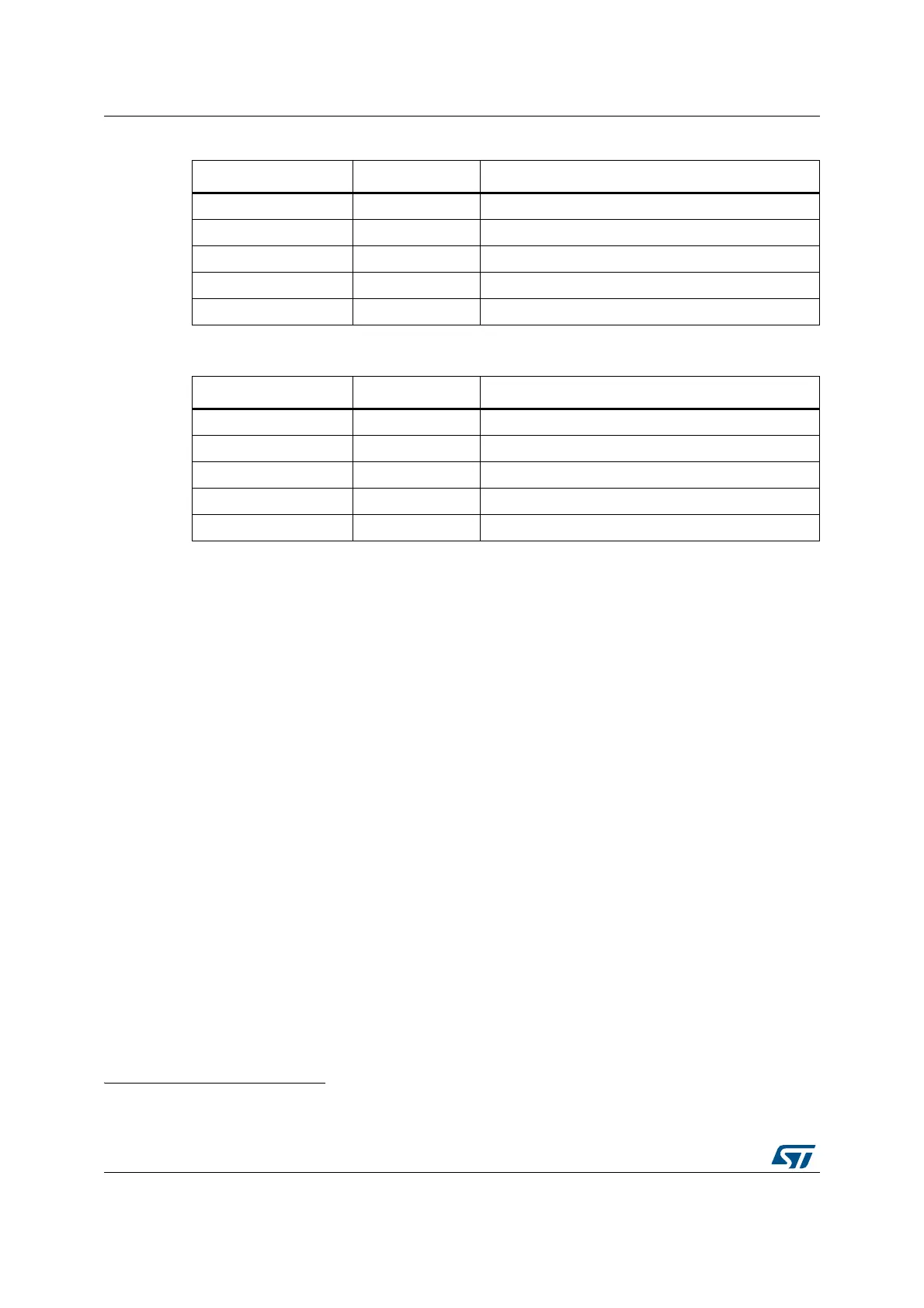
OTG_HS_ULPI_CK Digital input USB OTG ULPI clock
OTG_HS_ULPI_DIR Digital input USB OTG ULPI data bus direction control
OTG_HS_ULPI_STP Digital output USB OTG ULPI data stream stop
OTG_HS_ULPI_NXT Digital input USB OTG ULPI next data stream request
OTG_HS_ULPI_D[0..7] Digital input/output USB OTG ULPI 8-bit bi-directional data bus
Table 221. OTG_FS/OTG_HS input/output signals
Signal name Signal type Description
usb_sof Digital output USB OTG start-of-frame event for on chip peripherals
usb_wkup Digital output USB OTG wakeup event output
usb_gbl_it Digital output USB OTG global interrupt
usb_ep1_in_it Digital output USB OTG endpoint 1 in interrupt
usb_ep1_out_it Digital output USB OTG endpoint 1 out interrupt
Table 220. OTG_HS input/output pins (continued)
Signal name Signal type Description
a. The content of this section applies only to USB OTG FS.
 Loading...


