RM0390 Rev 4 467/1328
RM0390 Advanced-control timers (TIM1&TIM8)
520
Figure 133. Control circuit in external clock mode 1
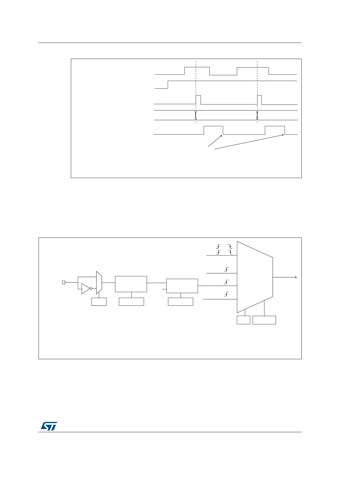
External clock source mode 2
This mode is selected by writing ECE=1 in the TIMx_SMCR register.
The counter can count at each rising or falling edge on the external trigger input ETR.
Figure 134 gives an overview of the external trigger input block.
Figure 134. External trigger input block
For example, to configure the upcounter to count each 2 rising edges on ETR, use the
following procedure:
&RXQWHUFORFN &.B&17 &.B36&
&RXQWHUUHJLVWHU
7,
&17B(1
7,)
:ULWH7,)
069
([WHUQDOFORFN
PRGH
,QWHUQDOFORFN
PRGH
75*,
&.B,17
&.B36&
7,0[B60&5
606>@
069
LQWHUQDOFORFN
7,) RU
7,) RU
RU
(QFRGHU
PRGH
([WHUQDOFORFN
PRGH
(75)
(&(
7,0[B60&5
(73
(75SLQ
(75
'LYLGHU
)LOWHU
GRZQFRXQWHU
I
(753
7,0[B60&5
(736>@
7,0[B60&5
(7)>@
'76