RM0390 Rev 4 947/1328
RM0390 Serial audio interface (SAI)
973
28.3.11 SPDIF output
The SPDIF interface is available in transmitter mode only. It supports the audio IEC60958.
To select SPDIF mode, set PRTCFG[1:0] bit to 01 in the SAI_xCR1 register.
For SPDIF protocol:
• Only SD data line is enabled.
• FS, SCK, MCLK I/Os pins are left free.
• MODE[1] bit is forced to 0 to select the master mode in order to enable the clock
generator of the SAI and manage the data rate on the SD line.
• The data size is forced to 24 bits. The value set in DS[2:0] bits in the SAI_xCR1 register
is ignored.
• The clock generator must be configured to define the symbol-rate, knowing that the bit
clock should be twice the symbol-rate. The data is coded in Manchester protocol.
• The SAI_xFRCR and SAI_xSLOTR registers are ignored. The SAI is configured
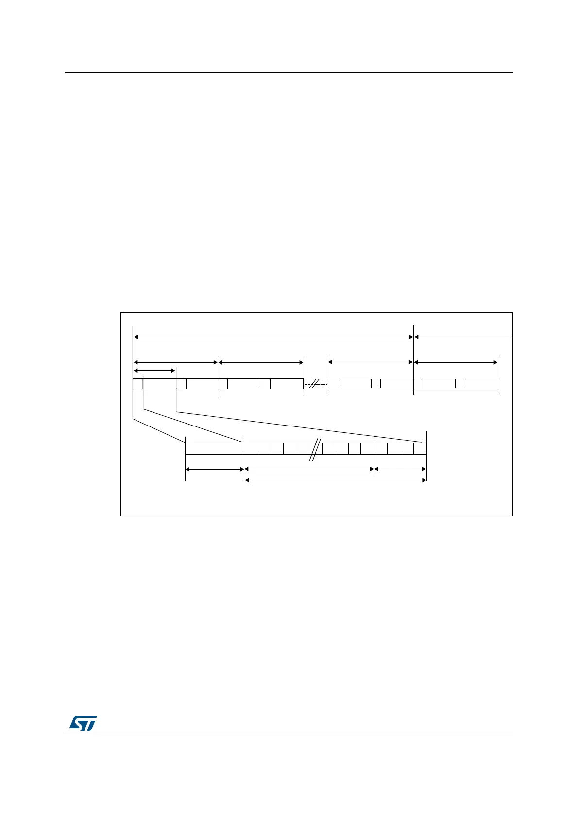
internally to match the SPDIF protocol requirements as shown in Figure 363.
Figure 363. SPDIF format
A SPDIF block contains 192 frames. Each frame is composed of two 32-bit sub-frames,
generally one for the left channel and one for the right channel. Each sub-frame is
composed of a SOPD pattern (4-bit) to specify if the sub-frame is the start of a block (and so
is identifying a channel A) or if it is identifying a channel A somewhere in the block, or if it is
referring to channel B (see Table 175). The next 28 bits of channel information are
composed of 24 bits data + 4 status bits.
%
&RAME &RAME &RAME
6XEIUDPH
623'
''
''
''
'
''
93
&6
8
3/0$"-7
#HANNEL
"LOCK.
"LOCK.
&RAME
BITDATA
3TATUSBIT
&KDQQHO$
:
&KDQQHO% 0
&KDQQHO$
:
&KDQQHO%
0
&KDQQHO$
:
&KDQQHO% %
&KDQQHO$
:
&KDQQHO%
-36
 Loading...


