RM0390 Rev 4 61/1328
RM0390
63
A mapping formula shows how to reference each word in the alias region to a corresponding
bit in the bit-band region. The mapping formula is:
bit_word_addr = bit_band_base + (byte_offset x 32) + (bit_number × 4)
where:
– bit_word_addr is the address of the word in the alias memory region that maps to
the targeted bit
– bit_band_base is the starting address of the alias region
– byte_offset is the number of the byte in the bit-band region that contains the
targeted bit
– bit_number is the bit position (0-7) of the targeted bit
Example
The following example shows how to map bit 2 of the byte located at SRAM address
0x20000300 to the alias region:
0x22006008 = 0x22000000 + (0x300*32) + (2*4)
Writing to address 0x22006008 has the same effect as a read-modify-write operation on bit
2 of the byte at SRAM address 0x20000300.
Reading address 0x22006008 returns the value (0x01 or 0x00) of bit 2 of the byte at SRAM
address 0x20000300 (0x01: bit set; 0x00: bit reset).
For more information on bit-banding, refer to the Cortex
®
-M4 with FPU programming
manual (see Related documents on page 1).
2.3 Boot configuration
Due to its fixed memory map, the code area starts from address 0x0000 0000 (accessed
through the ICode/DCode buses) while the data area (SRAM) starts from address
0x2000 0000 (accessed through the system bus). The Cortex
®
-M4 with FPU CPU always
fetches the reset vector on the ICode bus, which implies to have the boot area available only
in the code area (typically, Flash memory). STM32F446xx microcontrollers implement a
special mechanism to be able to boot from other memories (like the internal SRAM).
In the STM32F446xx, three different boot modes can be selected through the BOOT[1:0]
pins as shown in Table 2.
The values on the BOOT pins are latched on the 4th rising edge of SYSCLK after a reset. It
is up to the user to set the BOOT1 and BOOT0 pins after reset to select the required boot
mode.
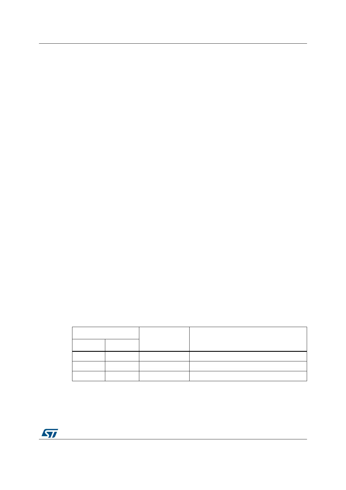
Table 2. Boot modes
Boot mode selection pins
Boot mode Aliasing
BOOT1 BOOT0
x 0 Main Flash memory Main Flash memory is selected as the boot area
0 1 System memory System memory is selected as the boot area
1 1 Embedded SRAM Embedded SRAM is selected as the boot area