Digital camera interface (DCMI) RM0390
428/1328 RM0390 Rev 4
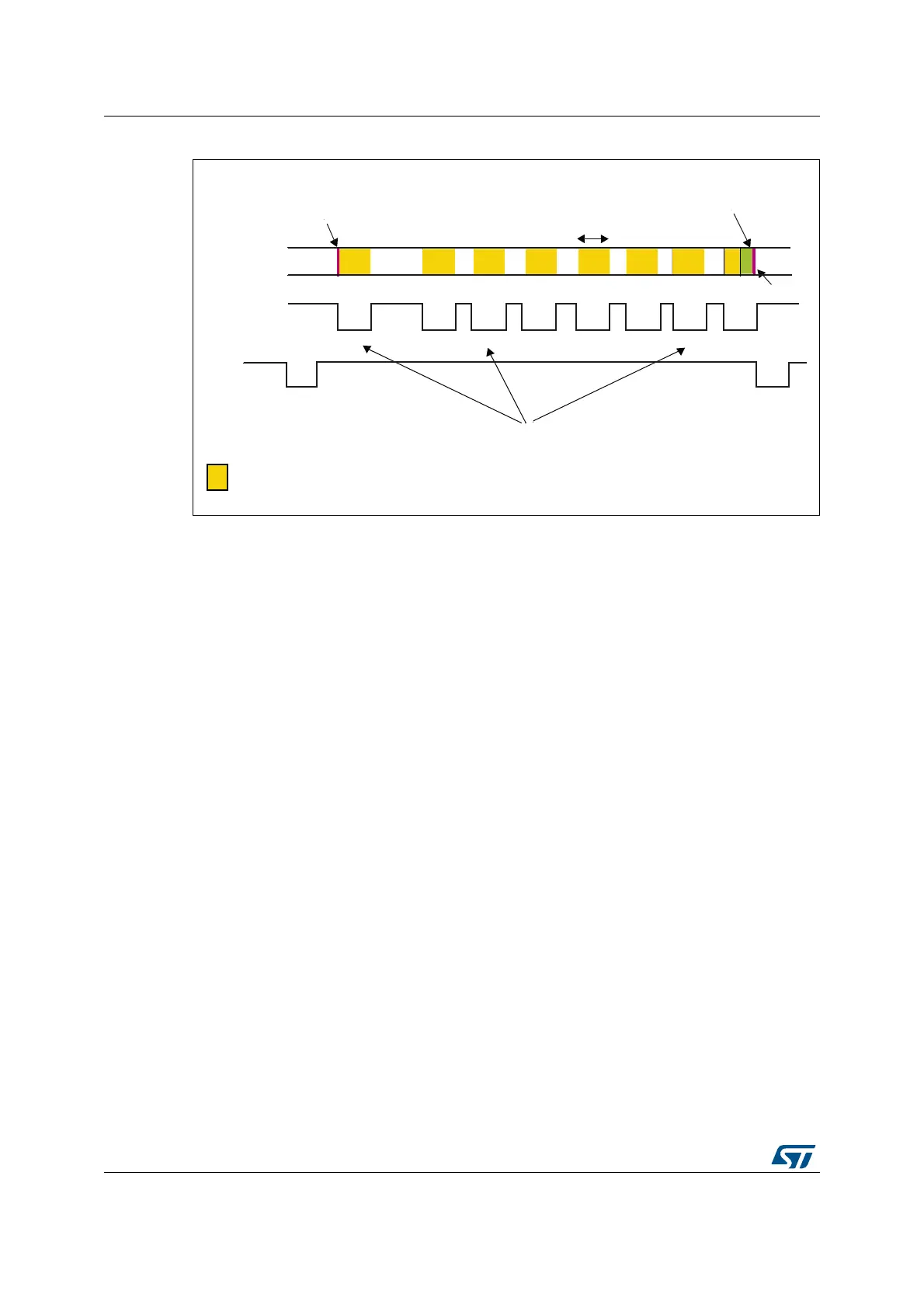
Figure 104. Timing diagram
Hardware synchronization mode
In hardware synchronization mode, the two synchronization signals
(DCMI_HSYNC/DCMI_VSYNC) are used.
Depending on the camera module/mode, data may be transmitted during horizontal/vertical
synchronization periods. The DCMI_HSYNC/DCMI_VSYNC signals act like blanking
signals since all the data received during DCMI_HSYNC/DCMI_VSYNC active periods are
ignored.
In order to correctly transfer images into the DMA/RAM buffer, data transfer is synchronized
with the DCMI_VSYNC signal. When the hardware synchronization mode is selected, and
capture is enabled (CAPTURE bit set in DCMI_CR), data transfer is synchronized with the
deactivation of the DCMI_VSYNC signal (next start of frame).
Transfer can then be continuous, with successive frames transferred by DMA to successive
buffers or the same/circular buffer. To allow the DMA management of successive frames, a
VSIF (Vertical synchronization interrupt flag) is activated at the end of each frame.
Embedded data synchronization mode
In this synchronization mode, the data flow is synchronized using 32-bit codes embedded in
the data flow. These codes use the 0x00/0xFF values that are not used in data anymore.
There are 4 types of codes, all with a 0xFF0000XY format. The embedded synchronization
codes are supported only in 8-bit parallel data width capture (in the DCMI_CR register, the
EDM[1:0] bits should be programmed to “00”). For other data widths, this mode generates
unpredictable results and must not be used.
DLE
%HJLQQLQJRI-3(*VWUHDP
-3(*GDWD
'&0,B+6<1&
-3(*SDFNHWGDWD
'&0,B96<1&
3DGGLQJGDWD
DWWKHHQGRIWKH-3(*VWUHDP
3URJUDPPDEOH
-3(*SDFNHWVL]H
(QGRI-3(*VWUHDP
3DFNHWGLVSDWFKLQJGHSHQGVRQWKHLPDJHFRQWHQW
7KLVUHVXOWVLQDYDULDEOHEODQNLQJGXUDWLRQ