RM0390 Rev 4 549/1328
RM0390 General-purpose timers (TIM2 to TIM5)
581
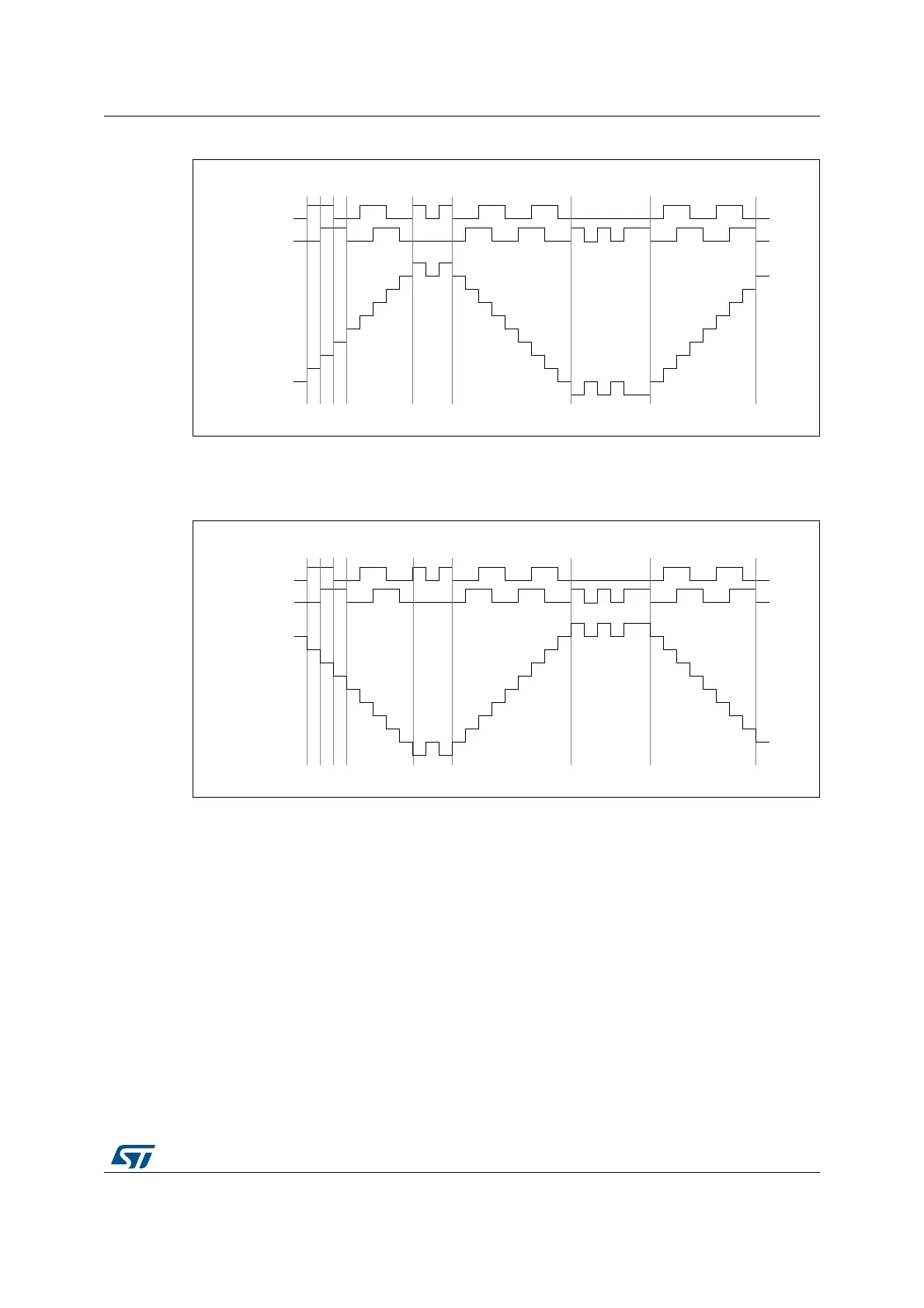
Figure 192. Example of counter operation in encoder interface mode
Figure 193 gives an example of counter behavior when TI1FP1 polarity is inverted (same
configuration as above except CC1P=1).
Figure 193. Example of encoder interface mode with TI1FP1 polarity inverted
The timer, when configured in Encoder Interface mode provides information on the sensor’s
current position. You can obtain dynamic information (speed, acceleration, deceleration) by
measuring the period between two encoder events using a second timer configured in
capture mode. The output of the encoder which indicates the mechanical zero can be used
for this purpose. Depending on the time between two events, the counter can also be read
at regular times. You can do this by latching the counter value into a third input capture
register if available (then the capture signal must be periodic and can be generated by
another timer). when available, it is also possible to read its value through a DMA request
generated by a Real-Time clock.
7,
EDFNZDUGMLWWHU MLWWHU
XS GRZQ XS
7,
&RXQWHU
IRUZDUG IRUZDUG
069
7,
EDFNZDUGMLWWHU MLWWHU
XSGRZQ
7,
&RXQWHU
IRUZDUG IRUZDUG
069
GRZQ