SPDIF receiver interface (SPDIFRX) RM0390
910/1328 RM0390 Rev 4
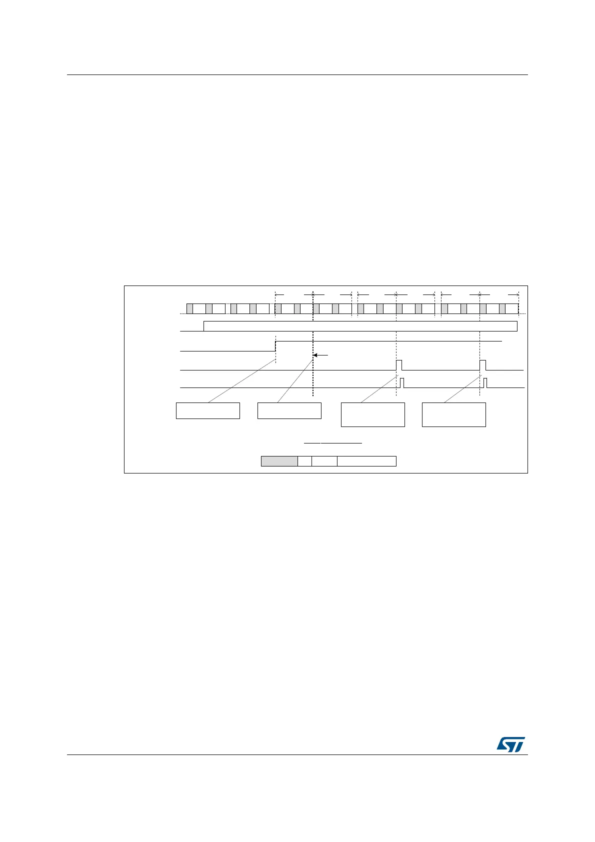
27.3.7 Dedicated control flow
The SPDIFRX offers the possibility to catch both user data and channel status information
via a dedicated DMA channel. This feature allows the SPDIFRX to acquire continuously the
channel status and user information. The acquisition will start at the beginning of a IEC
60958 block. Two fields are available to control this path: CBDMAEN and SPDIFRXEN.
When SPDIFRXEN is set to 0b01 or 0x11, the acquisition is started, after completion of the
synchronization phase. When 8 channel status and 16 user data bits have been received,
they are packed and stored into SPDIFRX_CSR register. A DMA request is triggered if the
bit CBDMAEN is set to 1 (see Figure 350).
If CS[0] corresponds to the first bit of a new block, the bit SOB will be set to 1. Refer to
Section 27.5.8: Channel status register (SPDIFRX_CSR). A bit is available (CHSEL) in
order to select if the user wants to select channel status information (C) from the channel A
or B.
Figure 350. Channel/user data format
Note: Once the first start of block is detected (B preamble), the SPDIFRX is checking the
preamble type every 8 frames.
Note: Overrun error on SPDIFRX_DR register does not affect this path.
27.3.8 Reception errors
Frame structure and synchronization error
The SPDIFRX, detects errors, when one of the following condition occurs:
• The FERR bit is set to 1 on the following conditions:
– For each of the 28 information bits, if one symbol transition sequence is not
correct: for example if short pulses are not grouped by pairs.
– If preambles occur to an unexpected place, or an expected preamble is not
received.
• The SERR bit is set when the synchronization fails, because the number of re-tries
exceeded the programmed value.
• The TERR bit is set when the counter used to estimate the width between two
transitions overflows (TRCNT).
0 $ : % % $ : % 0 $ : % % $ : % 0 $ : %
63',)5;B,1
0 $ : %
63',)5;(1
6<1&'
VSGLIU[BGPDBUHTBF
)UDPH )UDPH )UDPH
VSGLIU[BGPDBFOUBF
$FTXLVLWLRQRI&DQG8
ELWVVWDUWHG
6\QFKURQL]DWLRQGRQH
7UDQVIHURIILUVW
63',)5;B&%ZRUGZLWK
62%
)UDPH
0 $ : %
)UDPH
0 $ : %
)UDPH
7UDQVIHURIVHFRQG
63',)5;B&%ZRUGZLWK
62%
865>@&6>@62%UHVHUYHG
63',)5;B&65IRUPDW
ERUE
6WDUWRIDQHZEORFN
06Y9