RM0390 Rev 4 853/1328
RM0390 Serial peripheral interface/ inter-IC sound (SPI/I2S)
896
26.3.4 Multi-master communication
Unless SPI bus is not designed for a multi-master capability primarily, the user can use build
in feature which detects a potential conflict between two nodes trying to master the bus at
the same time. For this detection, NSS pin is used configured at hardware input mode.
The connection of more than two SPI nodes working at this mode is impossible as only one
node can apply its output on a common data line at time.
When nodes are non active, both stay at slave mode by default. Once one node wants to
overtake control on the bus, it switches itself into master mode and applies active level on
the slave select input of the other node via dedicated GPIO pin. After the session is
completed, the active slave select signal is released and the node mastering the bus
temporary returns back to passive slave mode waiting for next session start.
If potentially both nodes raised their mastering request at the same time a bus conflict event
appears (see mode fault MODF event). Then the user can apply some simple arbitration
process (e.g. to postpone next attempt by predefined different time-outs applied at both
nodes).
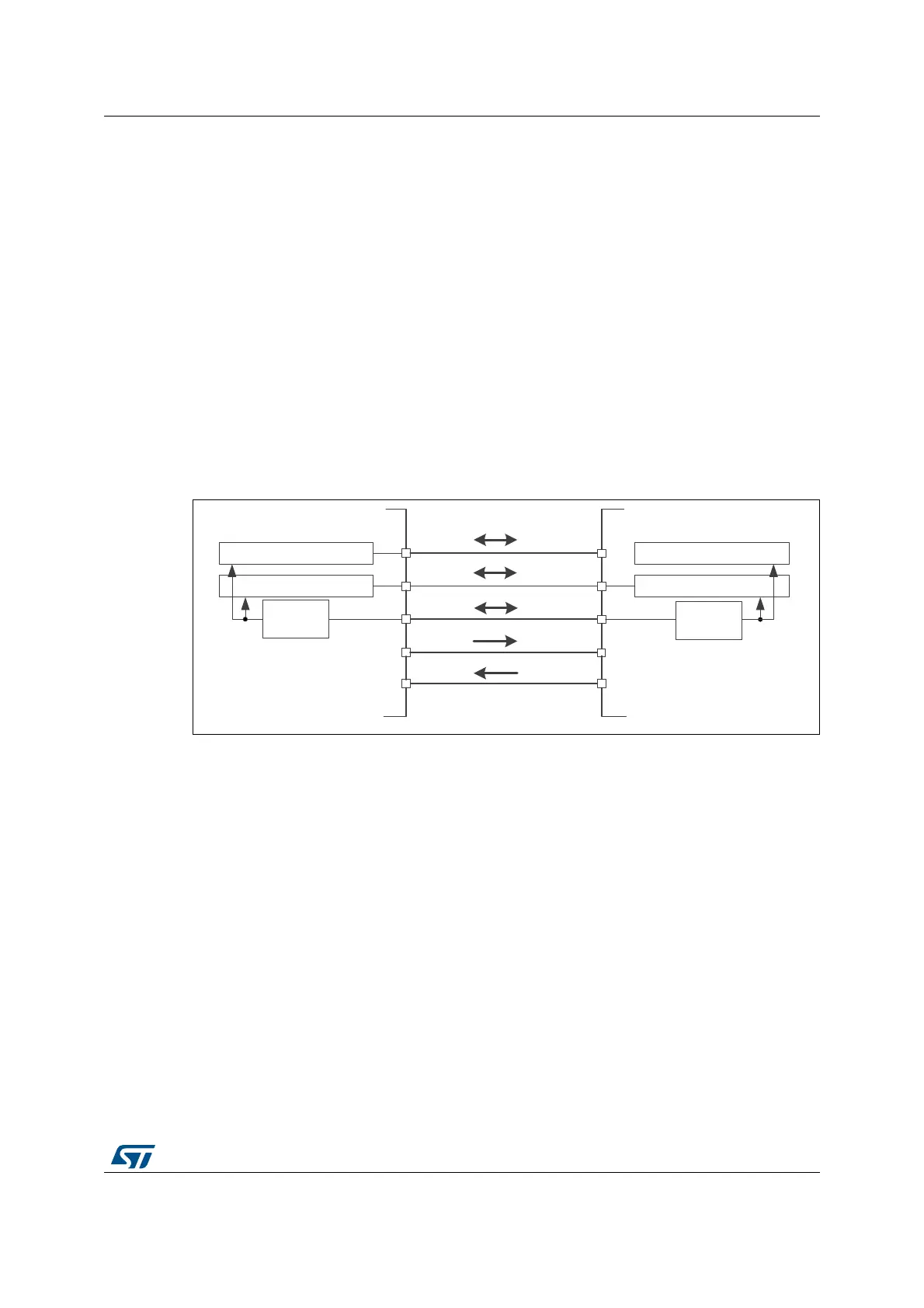
Figure 309. Multi-master application
1. The NSS pin is configured at hardware input mode at both nodes. Its active level enables the MISO line
output control as the passive node is configured as a slave.
26.3.5 Slave select (NSS) pin management
In slave mode, the NSS works as a standard “chip select” input and lets the slave
communicate with the master. In master mode, NSS can be used either as output or input.
As an input it can prevent multimaster bus collision, and as an output it can drive a slave
select signal of a single slave.
Hardware or software slave select management can be set using the SSM bit in the
SPIx_CR1 register:
• Software NSS management (SSM = 1): in this configuration, slave select information
is driven internally by the SSI bit value in register SPIx_CR1. The external NSS pin is
free for other application uses.
• Hardware NSS management (SSM = 0): in this case, there are two possible
configurations. The configuration used depends on the NSS output configuration
(SSOE bit in register SPIx_CR1).
5[7[VKLIWUHJLVWHU
7[5[VKLIWUHJLVWHU 7[5[VKLIWUHJLVWHU
5[7[VKLIWUHJLVWHU
63,FORFN
JHQHUDWRU
0DVWHU
6ODYH
DĂƐƚĞƌ
;^ůĂǀĞͿ
0,62
026,
6&.
166
0,62
026,
6&.
166
06Y9
63,FORFN
JHQHUDWRU
*3,2
*3,2