RM0390 Rev 4 885/1328
RM0390 Serial peripheral interface/ inter-IC sound (SPI/I2S)
896
ERRIE bit in the SPIx_CR2 register is set.
The UDR bit is cleared by a read operation on the SPIx_SR register.
Overrun flag (OVR)
This flag is set when data are received and the previous data have not yet been read from
the SPIx_DR register. As a result, the incoming data are lost. An interrupt may be generated
if the ERRIE bit is set in the SPIx_CR2 register.
In this case, the receive buffer contents are not updated with the newly received data from
the transmitter device. A read operation to the SPIx_DR register returns the previous
correctly received data. All other subsequently transmitted half-words are lost.
Clearing the OVR bit is done by a read operation on the SPIx_DR register followed by a
read access to the SPIx_SR register.
Frame error flag (FRE)
This flag can be set by hardware only if the I
2
S is configured in Slave mode. It is set if the
external master is changing the WS line while the slave is not expecting this change. If the
synchronization is lost, the following steps are required to recover from this state and
resynchronize the external master device with the I
2
S slave device:
1. Disable the I
2
S.
2. Enable it again when the correct level is detected on the WS line (WS line is high in I
2
S
mode or low for MSB- or LSB-justified or PCM modes.
Desynchronization between master and slave devices may be due to noisy environment on
the SCK communication clock or on the WS frame synchronization line. An error interrupt
can be generated if the ERRIE bit is set. The desynchronization flag (FRE) is cleared by
software when the status register is read.
26.6.9 I
2
S interrupts
Table 165 provides the list of I
2
S interrupts.
26.6.10 DMA features
In I
2
S mode, the DMA works in exactly the same way as it does in SPI mode. There is no
difference except that the CRC feature is not available in I
2
S mode since there is no data
transfer protection system.
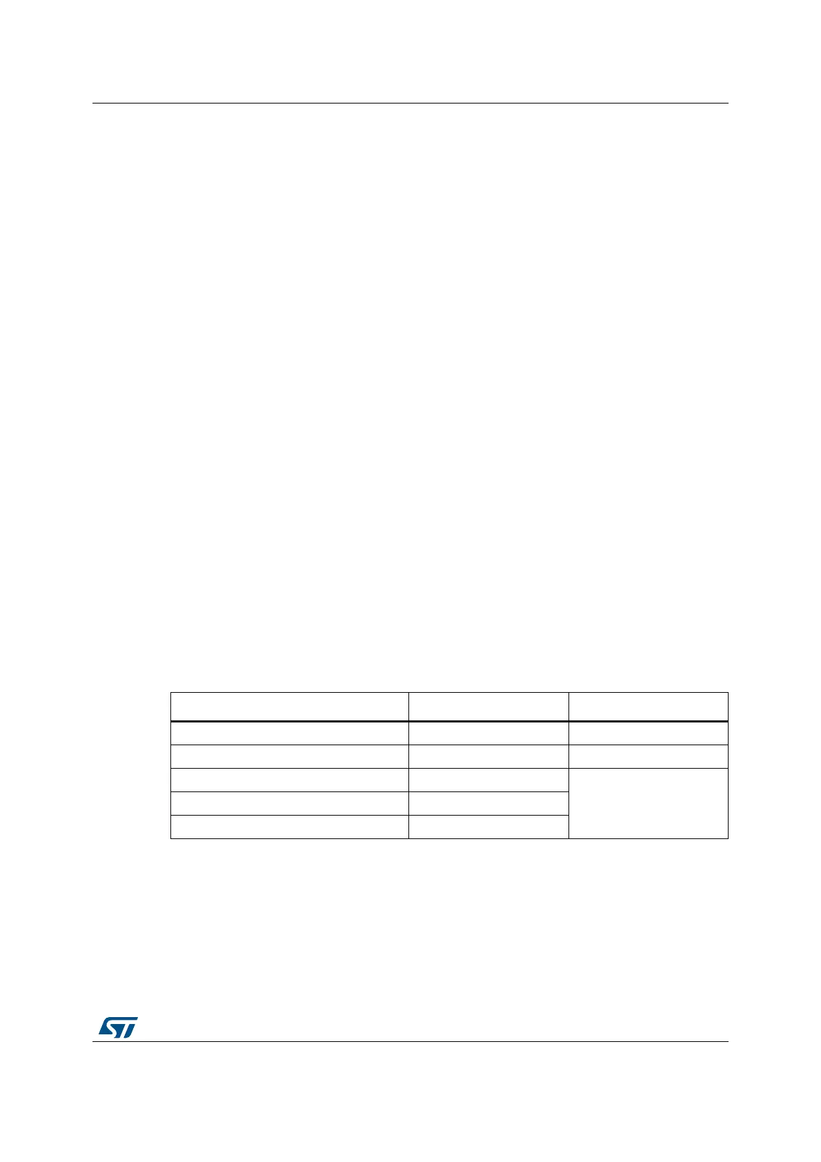
Table 165. I
2
S interrupt requests
Interrupt event Event flag Enable control bit
Transmit buffer empty flag TXE TXEIE
Receive buffer not empty flag RXNE RXNEIE
Overrun error OVR
ERRIEUnderrun error UDR
Frame error flag FRE
 Loading...


