RM0390 Rev 4 79/1328
RM0390 Embedded Flash memory interface
87
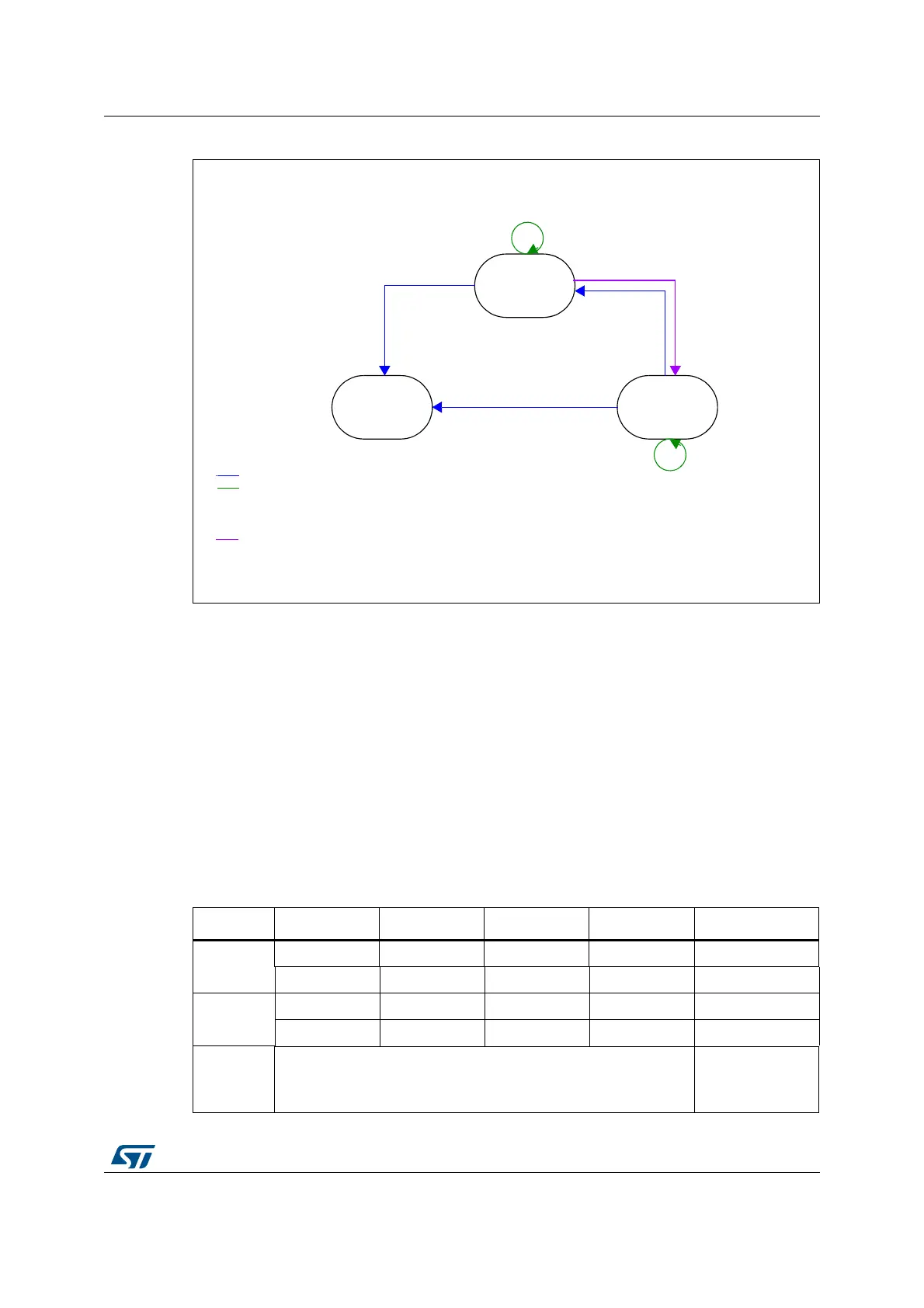
Figure 6. PCROP levels
The deactivation of the SPRMOD and/or the unprotection of PCROPed user sectors can
only occur when, at the same time, the RDP level changes from 1 to 0. If this condition is not
respected, the user option byte modification is canceled and the write error WRPERR flag is
set. The modification of the users option bytes (BOR_LEV, RST_STDBY, ..) is allowed since
none of the active nWRPi bits is reset and SPRMOD is kept active.
Note: The active value of nWRPi bits is inverted when PCROP mode is active (SPRMOD =1).
If SPRMOD = 1 and nWRPi =1, then user sector i of bank 1, respectively bank 2 is
read/write protected (PCROP).
3.7 One-time programmable bytes
Table 11 shows the organization of the one-time programmable (OTP) part of the OTP area.
,EVEL
,EVEL
2$0X##
2$0X!!
2$0X##
DEFAULT
5SEROPTIONSECTORERASE
0ROGRAMNEWOPTIONS
'LOBALMASSERASE
5SEROPTIONSECTIONERASE
0ROGRAMNEWOPTIONS
7RITEOPTIONS
30-/$ACTIVE
ANDVALIDN720I
.ORESTRICTIONON
7RITEOPTIONS
7RITEOPTIONS
30-/$ACTIVE
ANDVALIDN720I
,EVEL
2$0X!!
7RITEOPTIONS
30-/$ACTIVE
ANDVALIDN720I
7RITEOPTIONS
30-/$ACTIVE
ANDVALIDN720I
7RITEOPTIONS
30-/$ACTIVE
ANDVALIDN720I
6ALIDN720IMEANSTHATNONEOFTHEN720BITSSETCANBERESETTRANSITIONFROMTO
-36
Table 11. OTP area organization
Block [128:96] [95:64] [63:32] [31:0] Address byte 0
0
OTP0 OTP0 OTP0 OTP0 0x1FFF 7800
OTP0 OTP0 OTP0 OTP0 0x1FFF 7810
1
OTP1 OTP1 OTP1 OTP1 0x1FFF 7820
OTP1 OTP1 OTP1 OTP1 0x1FFF 7830
.
.
.
.
.
.
.
.
.