Serial audio interface (SAI) RM0390
936/1328 RM0390 Rev 4
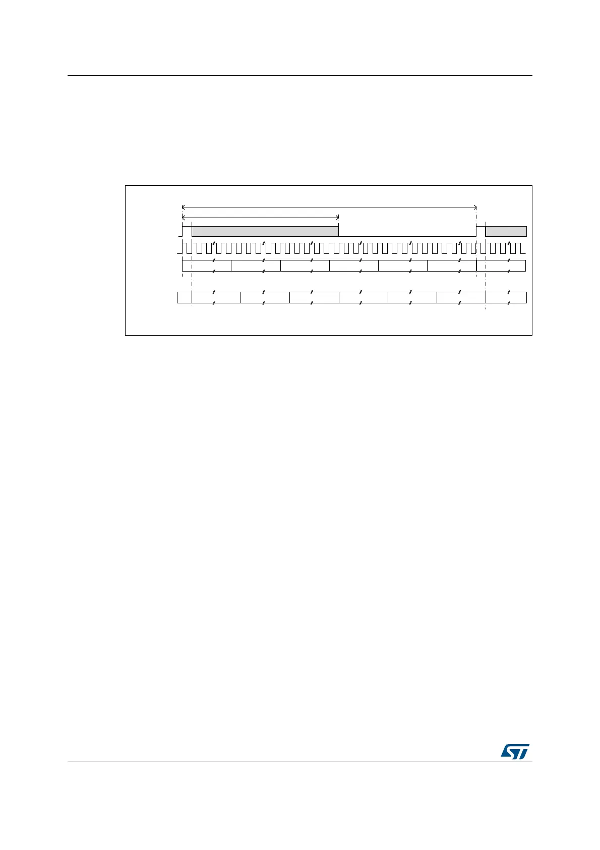
28.3.6 Frame synchronization
The FS signal acts as the Frame synchronization signal in the audio frame (start of frame).
The shape of this signal is completely configurable in order to target the different audio
protocols with their own specificities concerning this Frame synchronization behavior. This
reconfigurability is done using register SAI_xFRCR. Figure 355 illustrates this flexibility.
Figure 355. Audio frame
In AC’97 mode or in SPDIF mode (bit PRTCFG[1:0] = 10 or PRTCFG[1:0] = 01 in the
SAI_xCR1 register), the frame synchronization shape is forced to match the AC’97 protocol.
The SAI_xFRCR register value is ignored.
Each audio block is independent and consequently each one requires a specific
configuration.
Frame length
• Master mode
The audio frame length can be configured to up to 256 bit clock cycles, by setting
FRL[7:0] field in the SAI_xFRCR register.
If the frame length is greater than the number of declared slots for the frame, the
remaining bits to transmit will be extended to 0 or the SD line will be released to HI-z
depending the state of bit TRIS in the SAI_xCR2 register (refer to FS signal role). In
reception mode, the remaining bit is ignored.
If bit NODIV is cleared, (FRL+1) must be equal to a power of 2, from 8 to 256, to ensure
that an audio frame contains an integer number of MCLK pulses per bit clock cycle.
If bit NODIV is set, the (FRL+1) field can take any value from 8 to 256. Refer to
Section 28.3.8: SAI clock generator”.
• Slave mode
The audio frame length is mainly used to specify to the slave the number of bit clock
cycles per audio frame sent by the external master. It is used mainly to detect from the
master any anticipated or late occurrence of the Frame synchronization signal during
an on-going audio frame. In this case an error will be generated. For more details refer
to Section 28.3.13: Error flags.
In slave mode, there are no constraints on the FRL[7:0] configuration in the
SAI_xFRCR register.
The number of bits in the frame is equal to FRL[7:0] + 1.
The minimum number of bits to transfer in an audio frame is 8.
06Y9
7KHIDOOLQJHGJHFDQRFFXULQWRWKLVDUHD
6&.
6ORW 6ORW 6ORW 6ORW 6ORW « 6ORW
)6
6'
)62))
)6/HQJWKXSWRELWV
)6DFWLYHXSWRELWV
6ORW 6ORW 6ORW 6ORW 6ORW « 6ORW
6'
)62))
 Loading...


