SPDIF receiver interface (SPDIFRX) RM0390
918/1328 RM0390 Rev 4
27.5 SPDIFRX interface registers
27.5.1 Control register (SPDIFRX_CR)
Address offset: 0x00
Reset value: 0x0000 0000
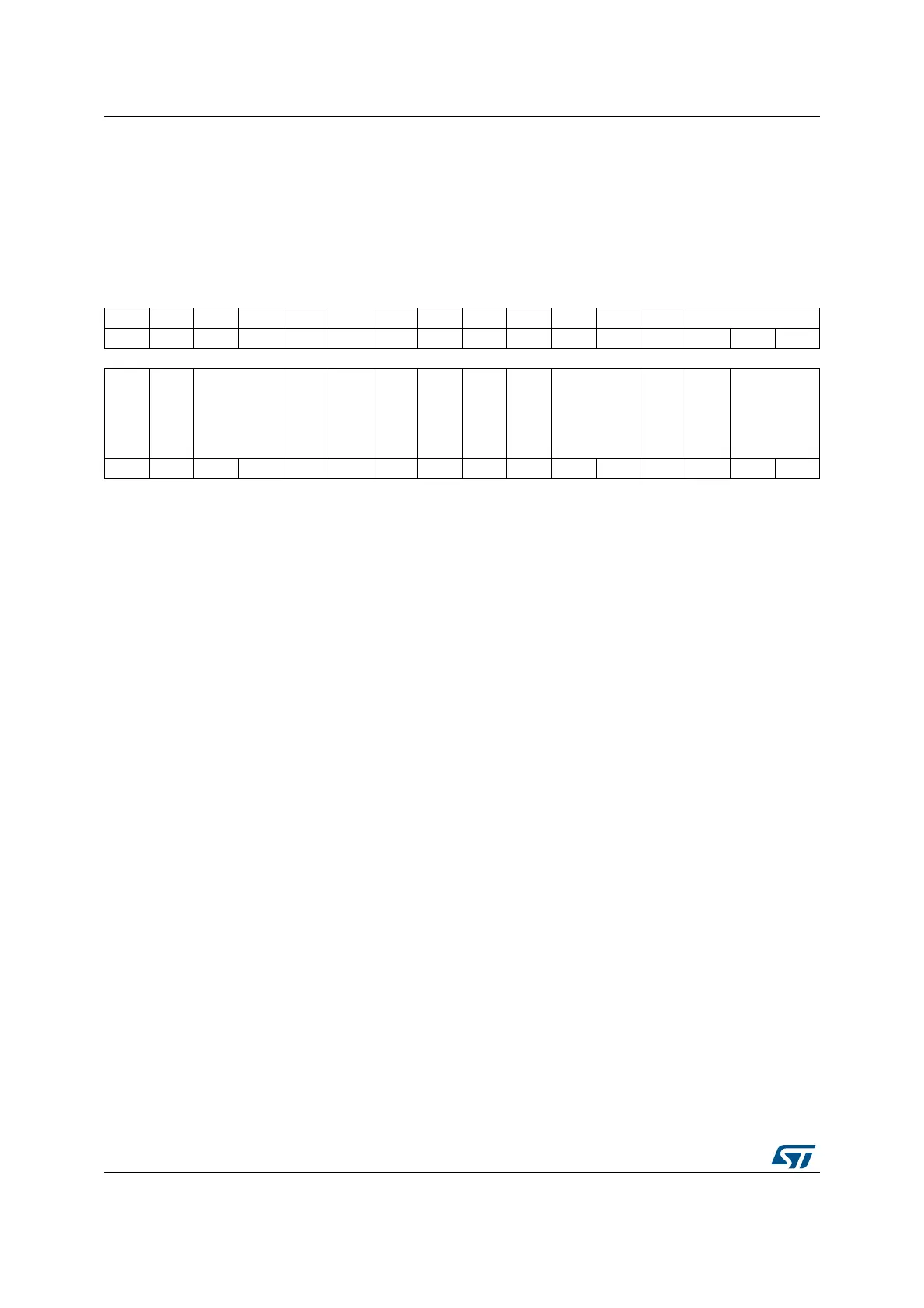
31 30 29 28 27 26 25 24 23 22 21 20 19 18 17 16
Res. Res. Res. Res. Res. Res. Res. Res. Res. Res. Res. Res. Res. INSEL[2:0]
rw rw rw
1514131211109876543210
Res.
WFA
NBTR[1:0]
CHSEL
CBDMAEN
PTMSK
CUMSK
VMSK
PMSK
DRFMT[1:0]
RXSTEO
RXDMAEN
SPDIFRXEN[1:0]
rw rw rw rw rw rw rw rw rw rw rw rw rw rw rw
Bits 31:19 Reserved, must be kept at reset value.
Bits 18:16 INSEL[2:0]: SPDIFRX input selection
(1)
0b000: SPDIFRX_IN1 selected
0b001: SPDIFRX_IN2 selected
0b010: SPDIFRX_IN3 selected
0b011: SPDIFRX_IN4 selected
others reserved
Bit 15 Reserved, must be kept at reset value.
Bit 14 WFA: Wait for activity
(1)
This bit is set/reset by software
1: The SPDIFRX waits for activity on SPDIFRX_IN line (4 transitions) before performing the
synchronization
0: The SPDIFRX does not wait for activity on SPDIFRX_IN line before performing the
synchronization
Bits 13:12 NBTR[1:0]: Maximum allowed re-tries during synchronization phase
(1)
0b00: No re-try is allowed (only one attempt)
0b01: 3 re-tries allowed
0b10: 15 re-tries allowed
0b11: 63 re-tries allowed
Bit 11 CHSEL: Channel selection
(1)
This bit is set/reset by software
1: The control flow will take the channel status from channel B
0: The control flow will take the channel status from channel A
Bit 10 CBDMAEN: Control buffer DMA enable for control flow
(1)
This bit is set/reset by software
1: DMA mode is enabled for reception of channel status and used data information.
0: DMA mode is disabled for reception of channel status and used data information.
When this bit is set, the DMA request is made whenever the CSRNE flag is set.
 Loading...


