RM0390 Rev 4 593/1328
RM0390 General-purpose timers (TIM9 to TIM14)
627
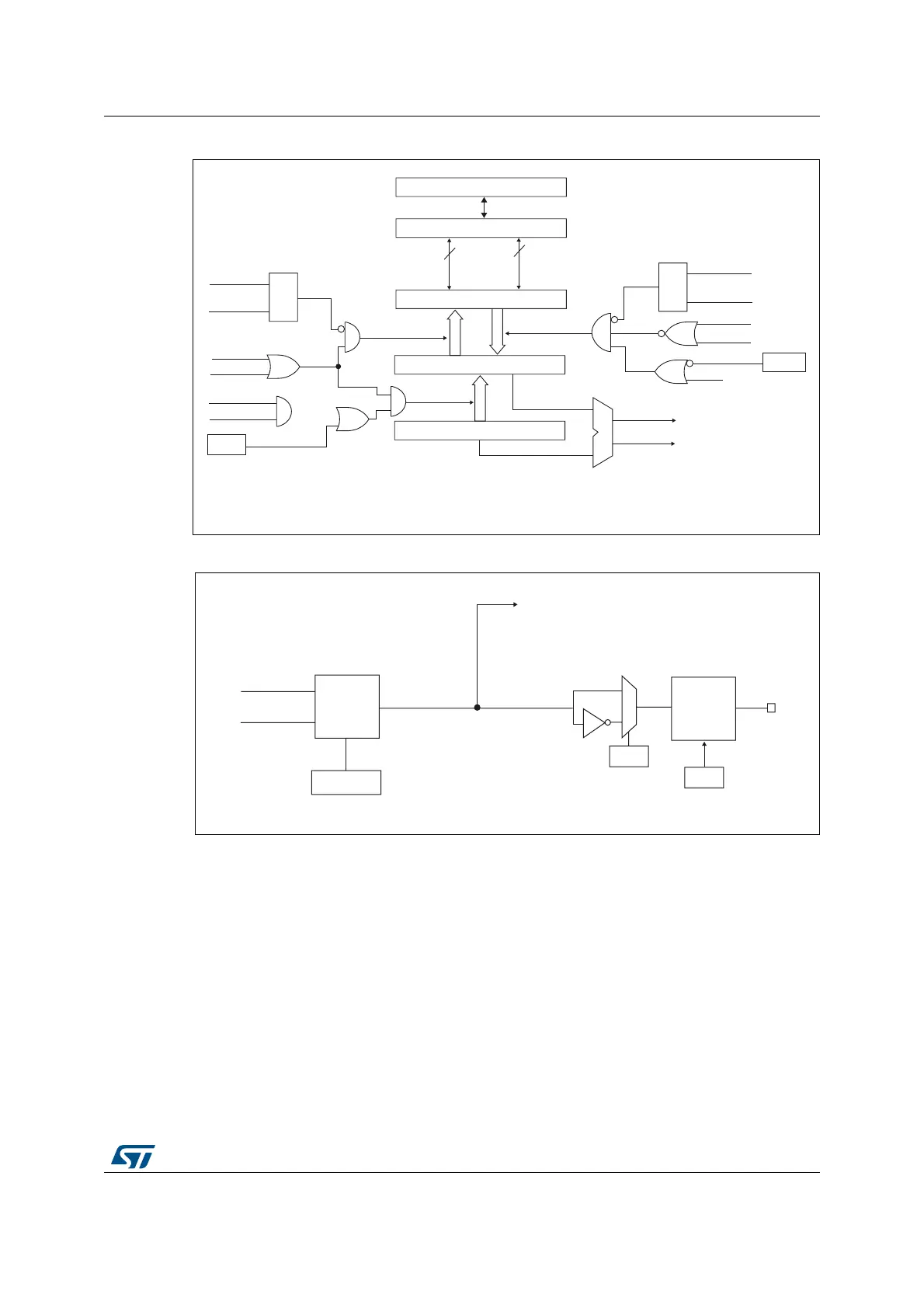
Figure 218. Capture/compare channel 1 main circuit
Figure 219. Output stage of capture/compare channel (channel 1)
The capture/compare block is made of one preload register and one shadow register. Write
and read always access the preload register.
In capture mode, captures are actually done in the shadow register, which is copied into the
preload register.
In compare mode, the content of the preload register is copied into the shadow register
which is compared to the counter.
18.3.5 Input capture mode
In Input capture mode, the Capture/Compare Registers (TIMx_CCRx) are used to latch the
value of the counter after a transition detected by the corresponding ICx signal. When a
capture occurs, the corresponding CCXIF flag (TIMx_SR register) is set and an interrupt or
a DMA request can be sent if they are enabled. If a capture occurs while the CCxIF flag was
already high, then the over-capture flag CCxOF (TIMx_SR register) is set. CCxIF can be
&&(
&DSWXUHFRPSDUHVKDGRZUHJLVWHU
&RPSDUDWRU
&DSWXUHFRPSDUHSUHORDGUHJLVWHU
&RXQWHU
,&36
&&6>@
&&6>@
&DSWXUH
,QSXW
PRGH
6
5
5HDG&&5+
5HDG&&5/
UHDGBLQBSURJUHVV
FDSWXUHBWUDQVIHU
&&6>@
&&6>@
6
5
ZULWH&&5+
ZULWH&&5/
ZULWHBLQBSURJUHVV
2XWSXW
PRGH
8(9
2&3(
IURPWLPH
EDVHXQLW
FRPSDUHBWUDQVIHU
$3%%XV
KLJK
ORZ
LIELW
0&8SHULSKHUDOLQWHUIDFH
7,0B&&05
2&3(
&17!&&5
&17 &&5
7,0B(*5
&&*
069
DL
2XWSXW
PRGH
FRQWUROOHU
&17!&&5
&17 &&5
7,0[B&&05
2&0>@
&&3
7,0[B&&(5
2XWSXW
HQDEOH
FLUFXLW
2&
&&(
7,0[B&&(5
7RWKHPDVWHU
PRGHFRQWUROOHU
2&B5()