RM0390 Rev 4 371/1328
RM0390 Analog-to-digital converter (ADC)
400
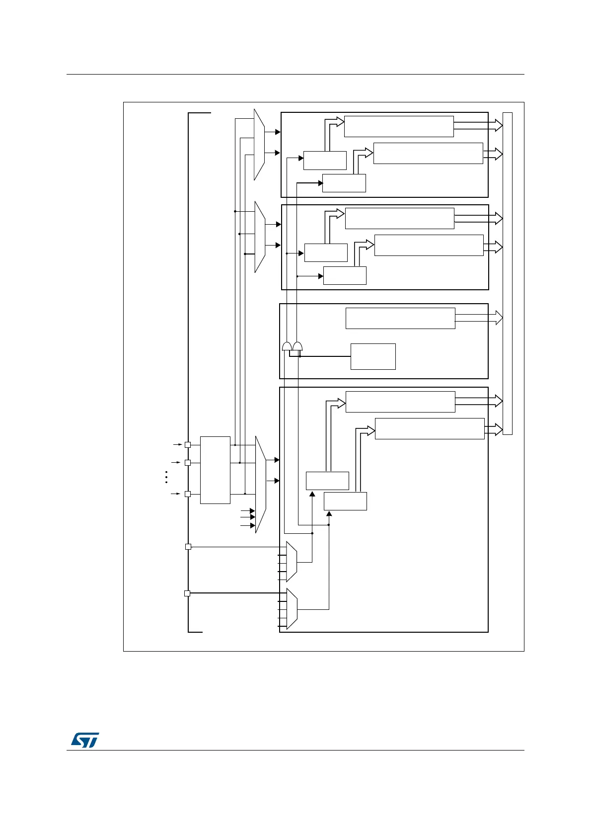
Figure 79. Multi ADC block diagram
(1)
1. Although external triggers are present on ADC2 and ADC3 they are not shown in this diagram.
2. In the Dual ADC mode, the ADC3 slave part is not present.
3. In Triple ADC mode, the ADC common data register (ADC_CDR) contains the ADC1, ADC2 and ADC3’s
regular converted data. All 32 register bits are used according to a selected storage order.
In Dual ADC mode, the ADC common data register (ADC_CDR) contains both the ADC1 and ADC2’s
regular converted data. All 32 register bits are used.
!$#X?).
!$#X?).
!$#X?).
'0)/
0ORTS
!DDRESSDATABUS
%84)?
%84)?
)NJECTEDDATAREGISTERS
XBITS
2EGULAR
CHANNELS
)NJECTED
CHANNELS
!$#
3LAVE
BITS
)NJECTEDDATAREGISTERS
XBITS
2EGULAR
CHANNELS
)NJECTED
CHANNELS
!$#-ASTER
$UAL4RIPLE
INTERNALTRIGGERS
3TARTTRIGGERMUX
REGULARGROUP
INJECTEDGROUP
3TARTTRIGGERMUX
CONTROL
4EMPSENSOR
6
2%&).4
2EGULARDATAREGISTER
BITS
2EGULARDATAREGISTER
BITS
#OMMONREGULARDATAREGISTER
BITS
6
"!4
#OMMONPART
MODE
!$#3LAVE
BITS
)NJECTEDDATAREGISTERS
XBITS
2EGULAR
CHANNELS
)NJECTED
CHANNELS
2EGULARDATAREGISTER
BITS
AI
 Loading...


