RM0390 Rev 4 1263/1328
RM0390 USB on-the-go full-speed/high-speed (OTG_FS/OTG_HS)
1264
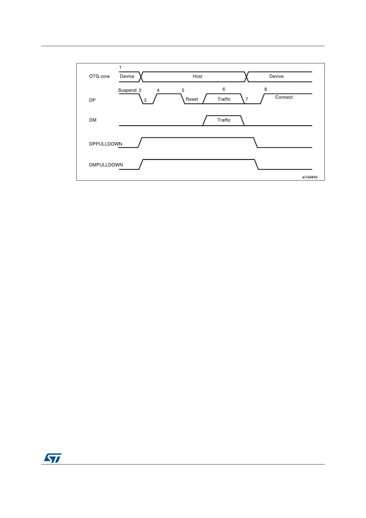
Figure 431. B-device HNP
1. DPPULLDOWN = signal from core to PHY to enable/disable the pull-down on the DP line inside the PHY.
DMPULLDOWN = signal from core to PHY to enable/disable the pull-down on the DM line inside the PHY.
The following points refer and describe the signal numeration shown in the Figure 431:
1. The A-device sends the SetFeature b_hnp_enable descriptor to enable HNP support.
The OTG_FS/OTG_HS controller’s ACK response indicates that it supports HNP. The
application must set the device HNP enable bit in the OTG control and status register
to indicate HNP support.
The application sets the HNP request bit in the OTG control and status register to
indicate to the OTG_FS/OTG_HS controller to initiate HNP.
2. When it has finished using the bus, the A-device suspends by writing the port suspend
bit in the host port control and status register.
The OTG_FS/OTG_HS controller sets the Early suspend bit in the core interrupt
register after 3 ms of bus idleness. Following this, the OTG_FS/OTG_HS controller
sets the USB suspend bit in the core interrupt register.
The OTG_FS/OTG_HS controller disconnects and the A-device detects SE0 on the
bus, indicating HNP. The OTG_FS/OTG_HS controller asserts the DP pull down and
DM pull down in the PHY to indicate its assumption of the host role.
The A-device responds by activating its OTG_DP pull-up resistor within 3 ms of
detecting SE0. The OTG_FS/OTG_HS controller detects this as a connect.
The OTG_FS/OTG_HS controller sets the host negotiation success status change
interrupt in the OTG interrupt status register, indicating the HNP status. The application
must read the host negotiation success bit in the OTG control and status register to
 Loading...


