Fast-mode Plus Inter-integrated circuit (FMPI2C) interface RM0390
696/1328 RM0390 Rev 4
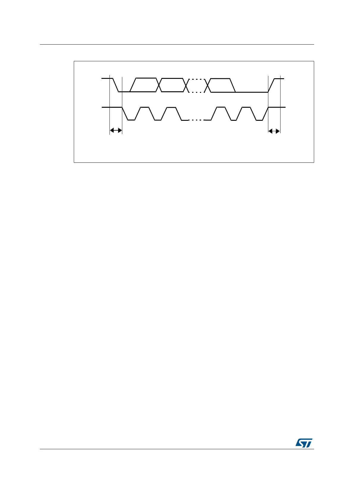
Figure 242. I
2
C bus protocol
Acknowledge can be enabled or disabled by software. The FMPI2C interface addresses can
be selected by software.
23.4.4 FMPI2C initialization
Enabling and disabling the peripheral
The FMPI2C peripheral clock must be configured and enabled in the clock controller (refer
to Section 6: Reset and clock control (RCC)).
Then the FMPI2C can be enabled by setting the PE bit in the FMPI2C_CR1 register.
When the FMPI2C is disabled (PE=0), the I
2
C performs a software reset. Refer to
Section 23.4.5: Software reset for more details.
Noise filters
Before enabling the FMPI2C peripheral by setting the PE bit in FMPI2C_CR1 register, the
user must configure the noise filters, if needed. By default, an analog noise filter is present
on the SDA and SCL inputs. This analog filter is compliant with the I
2
C specification which
requires the suppression of spikes with a pulse width up to 50 ns in Fast-mode and Fast-
mode Plus. The user can disable this analog filter by setting the ANFOFF bit, and/or select a
digital filter by configuring the DNF[3:0] bit in the FMPI2C_CR1 register.
When the digital filter is enabled, the level of the SCL or the SDA line is internally changed
only if it remains stable for more than DNF x FMPI2CCLK periods. This allows to suppress
spikes with a programmable length of 1 to 15 FMPI2CCLK periods.
Caution: Changing the filter configuration is not allowed when the FMPI2C is enabled.
069
6'$
6&/
6WDUW
FRQGLWLRQ
6WRS
FRQGLWLRQ
06% $&.