HDMI-CEC controller (HDMI-CEC) RM0390
1266/1328 RM0390 Rev 4
32.3 HDMI-CEC functional description
32.3.1 HDMI-CEC pin
The CEC bus consists of a single bidirectional line that is used to transfer data in and out of
the device. It is connected to a +3.3 V supply voltage via a 27 k pull-up resistor. The output
stage of the device must have an open-drain or open-collector to allow a wired-AND
connection.
The HDMI-CEC controller manages the CEC bidirectional line as an alternate function of a
standard GPIO, assuming that it is configured as Alternate Function Open Drain. The 27 k
pull-up must be added externally to the microcontroller.
To not interfere with the CEC bus when the application power is removed, it is mandatory to
isolate the CEC pin from the bus in such conditions. This could be done by using a MOS
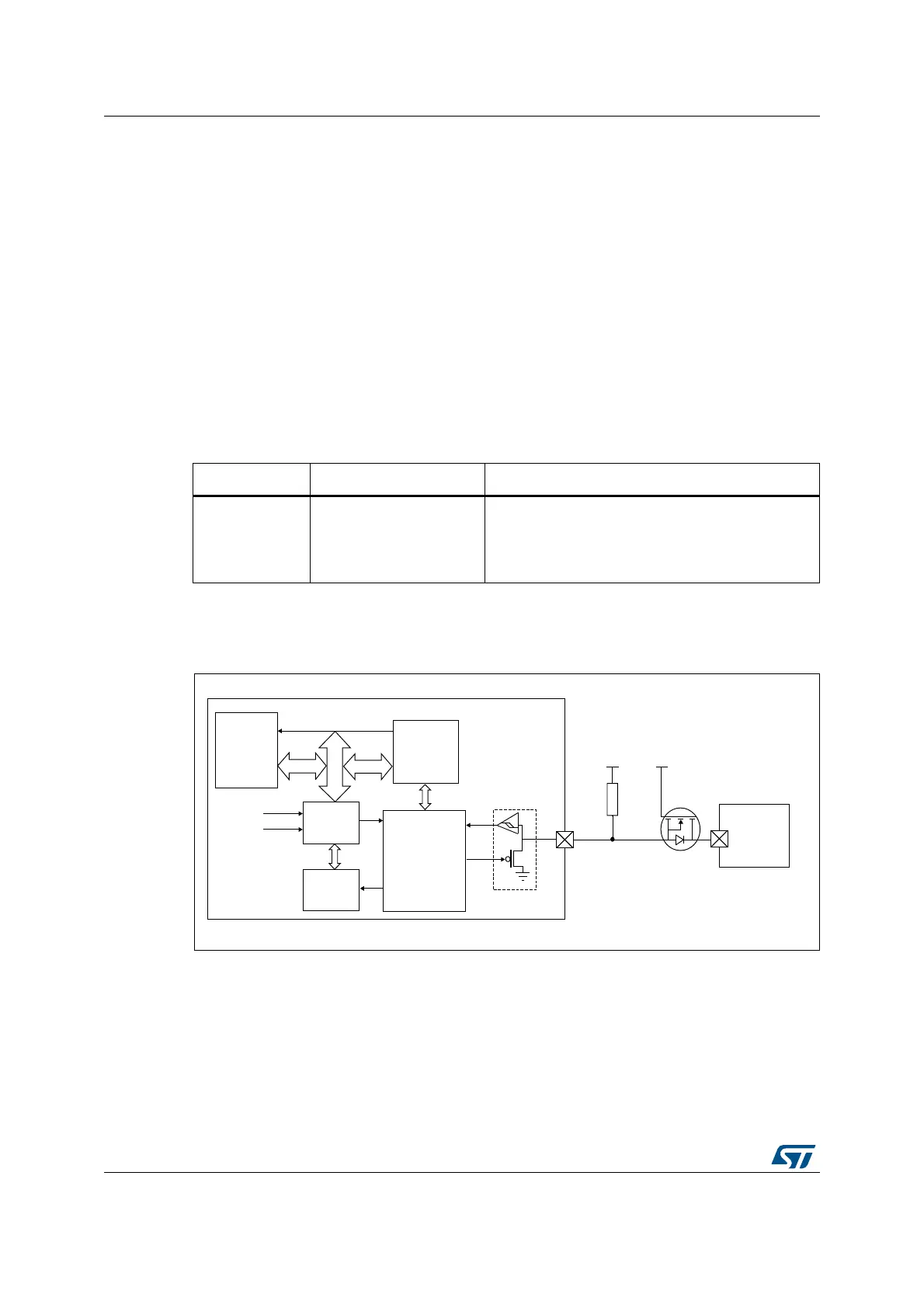
transistor, as shown on Figure 432.
32.3.2 HDMI-CEC block diagram
Figure 432. HDMI-CEC block diagram
Table 232. HDMI pin
Name Signal type Remarks
CEC Bidirectional
Two states:
– 1 = high impedance
– 0 = low impedance
A 27 k resistor must be added externally.
06Y9
&(&LQWHUUXSW
&RUH
&(&
GHYLFH
Nȍ
9
3$'
+6,
/6(
5&&
N+]
&(&
.HUQHO
$+%
(YHQW
FRQWURO
&(&
,7)
7;
5;&/.
:DNHLQW
*
6
'
&(&OLQH
670
+'0,B&(&
FRQWUROOHU
&RUWH[
$3%
9
5HPRWH
&(&
 Loading...


