Serial peripheral interface/ inter-IC sound (SPI/I2S) RM0390
872/1328 RM0390 Rev 4
The I
2
S interface supports four audio standards, configurable using the I2SSTD[1:0] and
PCMSYNC bits in the SPIx_I2SCFGR register.
I
2
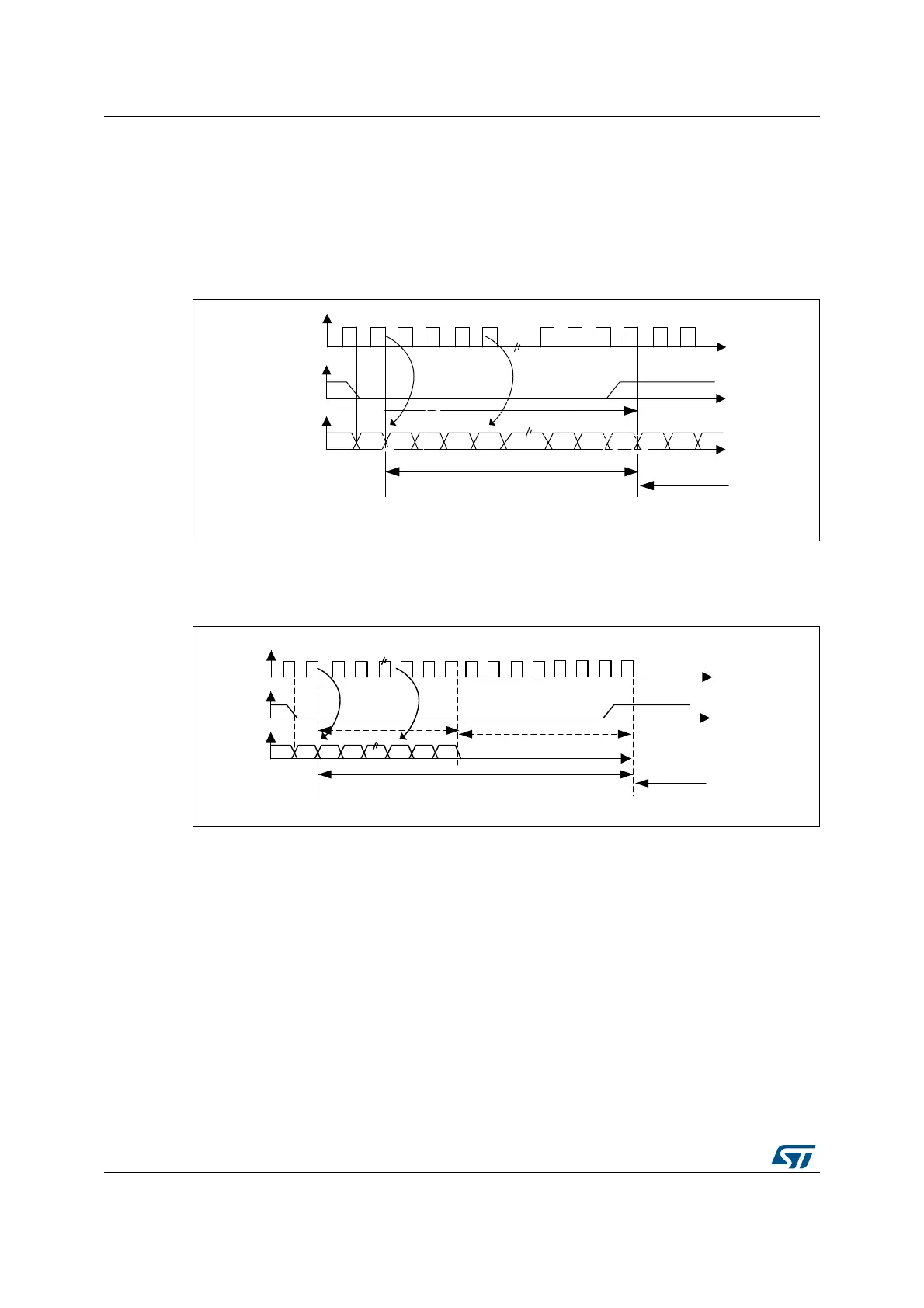
S Philips standard
For this standard, the WS signal is used to indicate which channel is being transmitted. It is
activated one CK clock cycle before the first bit (MSB) is available.
Figure 319. I
2
S Philips protocol waveforms (16/32-bit full accuracy, CPOL = 0)
Data are latched on the falling edge of CK (for the transmitter) and are read on the rising
edge (for the receiver). The WS signal is also latched on the falling edge of CK.
Figure 320. I
2
S Philips standard waveforms (24-bit frame with CPOL = 0)
This mode needs two write or read operations to/from the SPIx_DR register.
069
&.
:6
6'
&DQEHELWRUELW
06%
06%/6%
&KDQQHOOHIW
&KDQQHO
ULJKW
WUDQVPLVVLRQ UHFHSWLRQ
069
&.
:6
6'
7UDQVPLVVLRQ 5HFHSWLRQ
ELWGDWD
06%
/6%
&KDQQHOOHIWELW
&KDQQHOULJKW
ELWUHPDLQLQJIRUFHG
 Loading...


