RM0390 Rev 4 381/1328
RM0390 Analog-to-digital converter (ADC)
400
When not in use, the sensor can be put in power down mode.
Note: The TSVREFE bit must be set to enable the conversion of both internal channels: the
ADC1_IN18 (temperature sensor) and the ADC1_IN17 (VREFINT).
Main features
• Supported temperature range: –40 to 125 °C
• Precision: ±1.5 °C
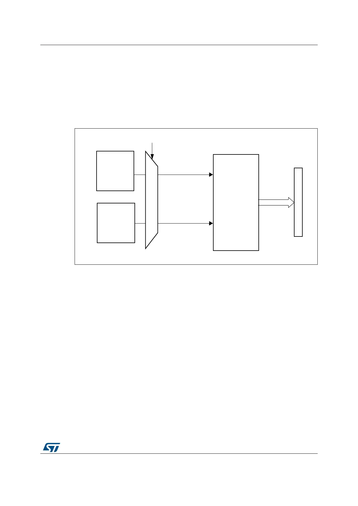
Figure 91. Temperature sensor and V
REFINT
channel block diagram
1. V
SENSE
is input to ADC1_IN18.
Reading the temperature
To use the sensor:
3. Select ADC1_IN18 input channel.
4. Select a sampling time greater than the minimum sampling time specified in the
datasheet.
5. Set the TSVREFE bit in the ADC_CCR register to wake up the temperature sensor
from power down mode
6. Start the ADC conversion by setting the SWSTART bit (or by external trigger)
7. Read the resulting V
SENSE
data in the ADC data register
8. Calculate the temperature using the following formula:
Temperature (in °C) = {(V
SENSE
– V
25
) / Avg_Slope} + 25
Where:
–V
25
= V
SENSE
value for 25° C
– Avg_Slope = average slope of the temperature vs. V
SENSE
curve (given in mV/°C
or µV/°C)
Refer to the datasheet electrical characteristics section for the actual values of V
25
and
Avg_Slope.
069
7HPSHUDWXUH
VHQVRU
9
6(16(
7695()(FRQWUROELW
$'&
$GGUHVVGDWDEXV
9
5(),17
$'&B,1
,QWHUQDO
SRZHUEORFN
$'&B,1
FRQYHUWHGGDWD