Digital camera interface (DCMI) RM0390
434/1328 RM0390 Rev 4
15.5.3 RGB format
Characteristics:
• Raster format
• RGB
• Interleaved: one buffer: R, G & B interleaved: BRGBRGBRG, etc.
• Optimized for display output
The RGB planar format is compatible with standard OS frame buffer display formats.
Only 16 BPP (bits per pixel): RGB565 (2 pixels per 32-bit word) is supported.
The 24 BPP (palletized format) and grayscale formats are not supported. Pixels are stored
in a raster scan order, that is from top to bottom for pixel rows, and from left to right within a
pixel row. Pixel components are R (red), G (green) and B (blue). All components have the
same spatial resolution (4:4:4 format). A frame is stored in a single part, with the
components interleaved on a pixel basis.
Table 102 shows how the data are stored.
15.5.4 YCbCr format
Characteristics:
• Raster format
• YCbCr 4:2:2
• Interleaved: one Buffer: Y, Cb & Cr interleaved: CbYCrYCbYCr, etc.
Pixel components are Y (luminance or “luma”), Cb and Cr (chrominance or “chroma” blue
and red). Each component is encoded in 8 bits. Luma and chroma are stored together
(interleaved) as shown in Table 103.
15.5.5 YCbCr format - Y only
Characteristics:
• Raster format
• YCbCr 4:2:2
• The buffer only contains Y information - monochrome image
Pixel components are Y (luminance or “luma”), Cb and Cr (chrominance or “chroma” blue
and red). In this mode, the chroma information is dropped. Only Luma component of each
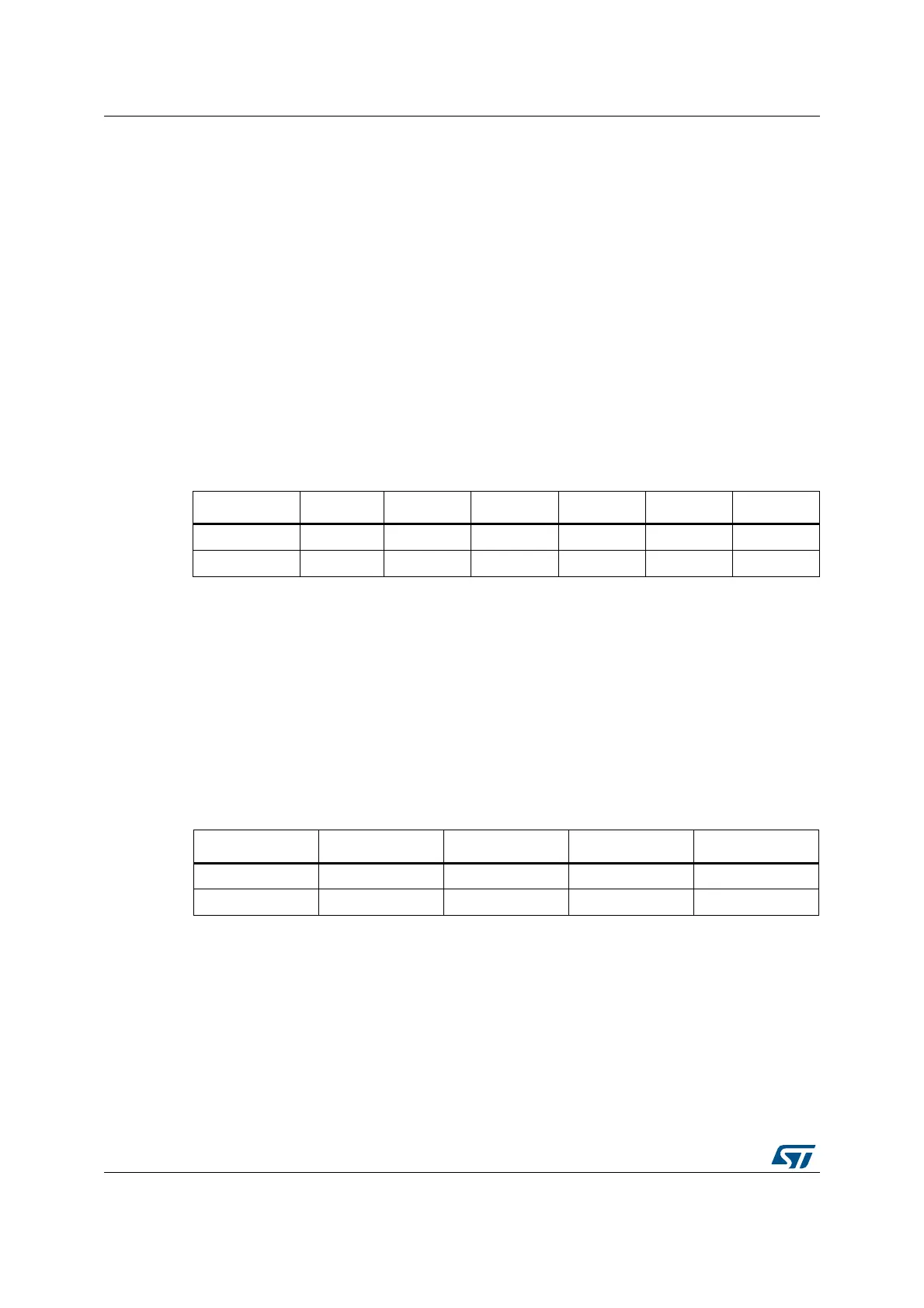
Table 102. Data storage in RGB progressive video format
Byte address 31:27 26:21 20:16 15:11 10:5 4:0
0 Red n + 1 Green n + 1 Blue n + 1 Red n Green n Blue n
4 Red n + 4 Green n + 3 Blue n + 3 Red n + 2 Green n + 2 Blue n + 2
Table 103. Data storage in YCbCr progressive video format
Byte address 31:24 23:16 15:8 7:0
0Y n + 1Cr n Y nCb n
4 Y n + 3 Cr n + 2 Y n + 2 Cb n + 2
 Loading...


