Serial audio interface (SAI) RM0390
948/1328 RM0390 Rev 4
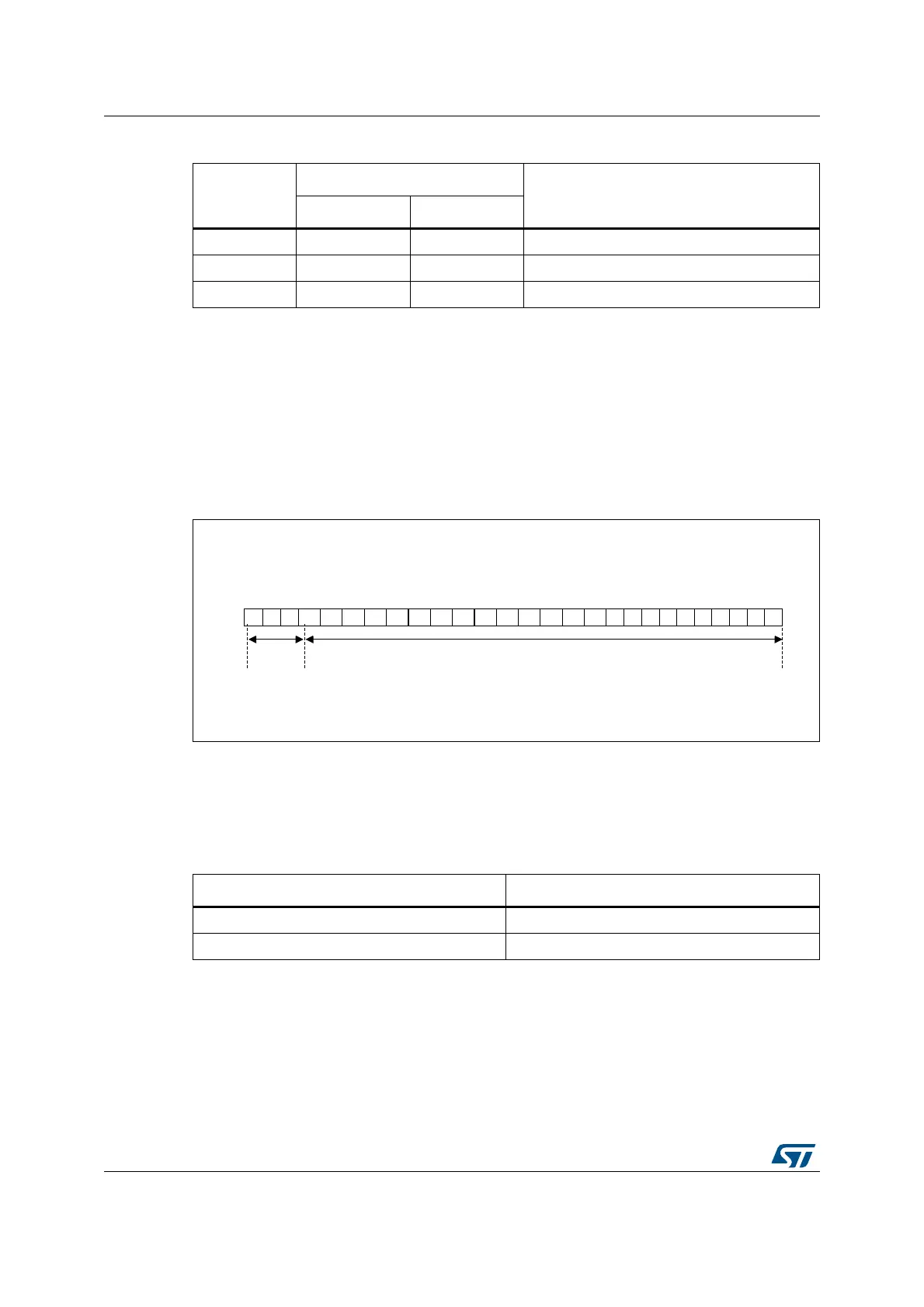
The data stored in SAI_xDR has to be filled as follows:
• SAI_xDR[26:24] contain the Channel status, User and Validity bits.
• SAI_xDR[23:0] contain the 24-bit data for the considered channel.
If the data size is 20 bits, then data shall be mapped on SAI_xDR[23:4].
If the data size is 16 bits, then data shall be mapped on SAI_xDR[23:8].
SAI_xDR[23] always represents the MSB.
Figure 364. SAI_xDR register ordering
Note: The transfer is performed always with LSB first.
The SAI first sends the adequate preamble for each sub-frame in a block. The SAI_xDR is
then sent on the SD line (manchester coded). The SAI ends the sub-frame by transferring
the Parity bit calculated as described in Table 176.
The underrun is the only error flag available in the SAI_xSR register for SPDIF mode since
the SAI can only operate in transmitter mode. As a result, the following sequence should be
Table 175. SOPD pattern
SOPD
Preamble coding
Description
last bit is 0 last bit is 1
B 11101000 00010111 Channel A data at the start of block
W 11100100 00011011 Channel B data somewhere in the block
M 11100010 00011101 Channel A data
06Y9
6$,B['5>@
' ' ' ' ' ' ' ' ' ' ' ' ' ' ' ' '&6 8 9
'DWD>@
6WDWXV
ELWV
'
' ' ' ' ''
Table 176. Parity bit calculation
SAI_xDR[26:0] Parity bit P value transferred
odd number of 0 0
odd number of 1 1