RM0390 Rev 4 425/1328
RM0390 Digital camera interface (DCMI)
448
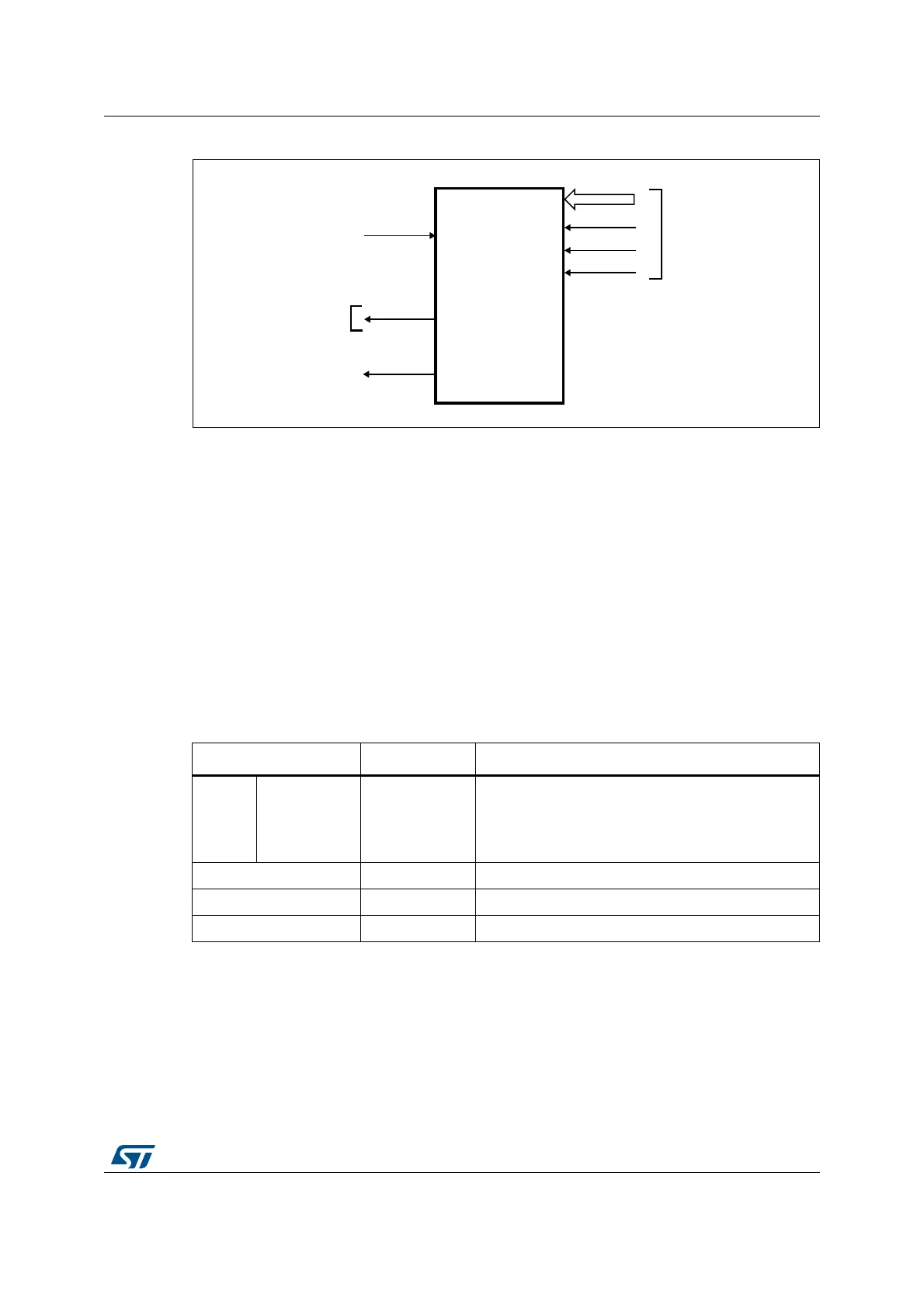
Figure 102. Top-level block diagram
15.4.2 DMA interface
The DMA interface is active when the CAPTURE bit in the DCMI_CR register is set. A DMA
request is generated each time the camera interface receives a complete 32-bit data block
in its register.
15.4.3 DCMI physical interface
The interface is composed of 11/13/15/17 inputs. Only the Slave mode is supported.
The camera interface can capture 8-bit, 10-bit, 12-bit or 14-bit data depending on the
EDM[1:0] bits in the DCMI_CR register. If less than 14 bits are used, the unused input pins
must be connected to ground.
Table 96 shows the DCMI pins.
The data are synchronous with DCMI_PIXCLK and change on the rising/falling edge of the
pixel clock depending on the polarity.
The DCMI_HSYNC signal indicates the start/end of a line.
The DCMI_VSYNC signal indicates the start/end of a frame
$#-)
)NTERRUPT
CONTROLLER
$#-)?)4
%XTERNAL
INTERFACE
$#-)?$;=
$#-)?0)8#,+
$#-)?(39.#
$#-)?639.#
$-!?2%1
(#,+
AIB
Table 96. DCMI external signals
Signal name Signal type Signal description
8 bits
10 bits
12 bits
14 bits
DCMI_D[0..7]
DCMI_D[0..9]
DCMI_D[0..11]
DCMI_D[0..13]
Digital inputs DCMI data
DCMI_PIXCLK Digital input Pixel clock
DCMI_HSYNC Digital input Horizontal synchronization / Data valid
DCMI_VSYNC Digital input Vertical synchronization